
Correcting for near-end crosstalk unbalance caused by deployment of crosstalk compensation on other pairs

a crosstalk compensation and near-end technology, applied in the direction of coupling device connection, two-part coupling device, electrical apparatus, etc., can solve the problems disturbing crosstalk of compensating coupling devi

Inactive Publication Date: 2005-03-15
COMMSCOPE INC
View PDF12 Cites 113 Cited by
  • Summary
  • Abstract
  • Description
  • Claims
  • Application Information

AI Technical Summary

Benefits of technology

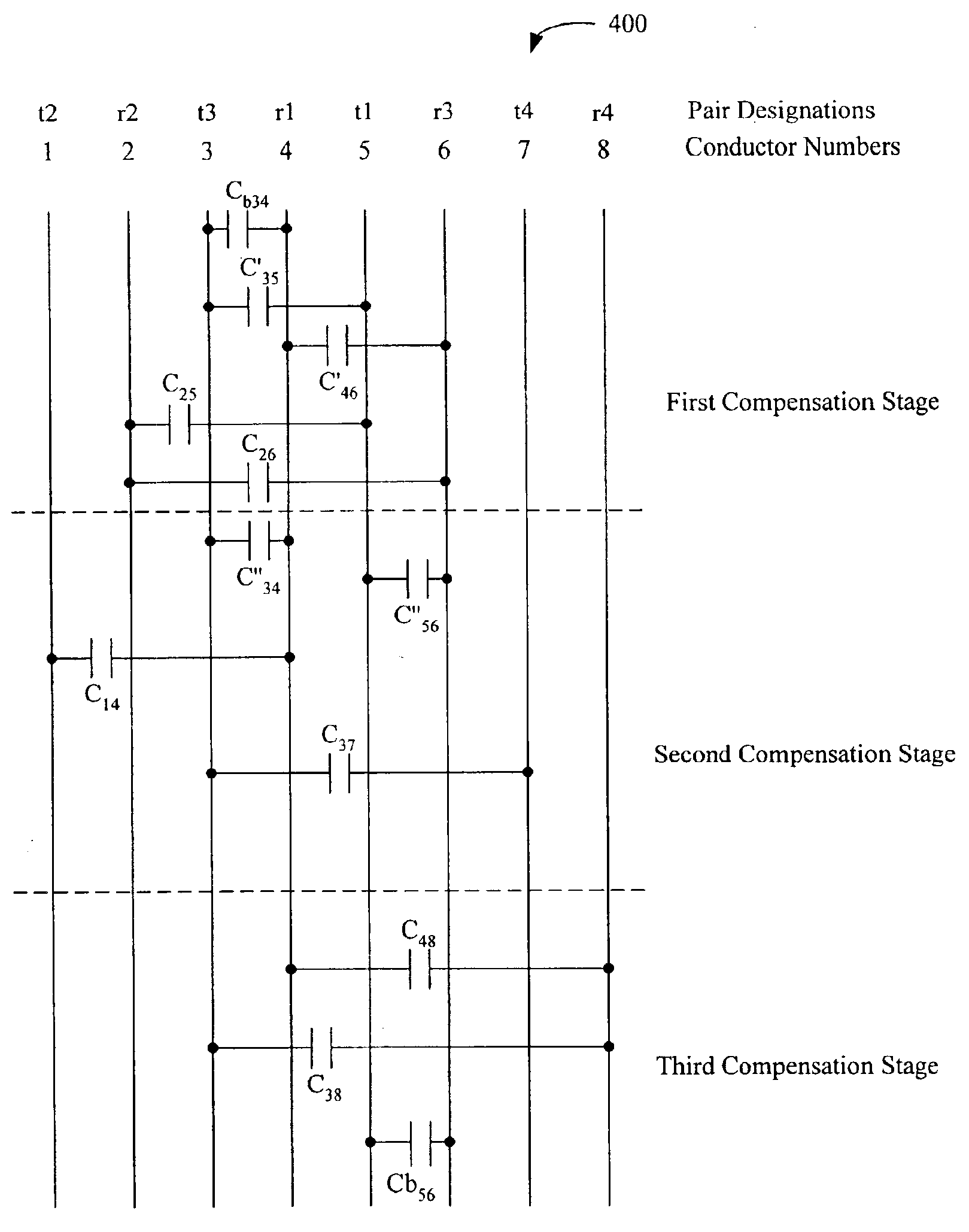
In accordance with one aspect of the present invention, a system for balancing crosstalk in an electrical connector with the following features is provided. The electrical connector has three or more pairs of conductors, wherein two pairs of conductors form a pair combination. The connector also has at least one compensating coupling device connected between the two pairs of conductors in a first pair combination. The compensating coupling device disturbs the crosstalk balance of a second pair combination. Thus, one embodiment of the present invention provides a system to compensate for the crosstalk disturbance in the connector caused by the compensating coupling device. The system includes at least one corrective coupling device connected between the two pairs of conductors in the second pair combination. In addition, one or more compensating coupling devices connected between the two pairs of conductors in the second pair combination are to counteract any crosstalk disturbances caused by one or more of the corrective coupling device.

Problems solved by technology

The compensating coupling device disturbs the crosstalk balance of a second pair combination.

Method used


Image

  • Correcting for near-end crosstalk unbalance caused by deployment of crosstalk compensation on other pairs
  • Correcting for near-end crosstalk unbalance caused by deployment of crosstalk compensation on other pairs
  • Correcting for near-end crosstalk unbalance caused by deployment of crosstalk compensation on other pairs

Examples


Embodiment Construction

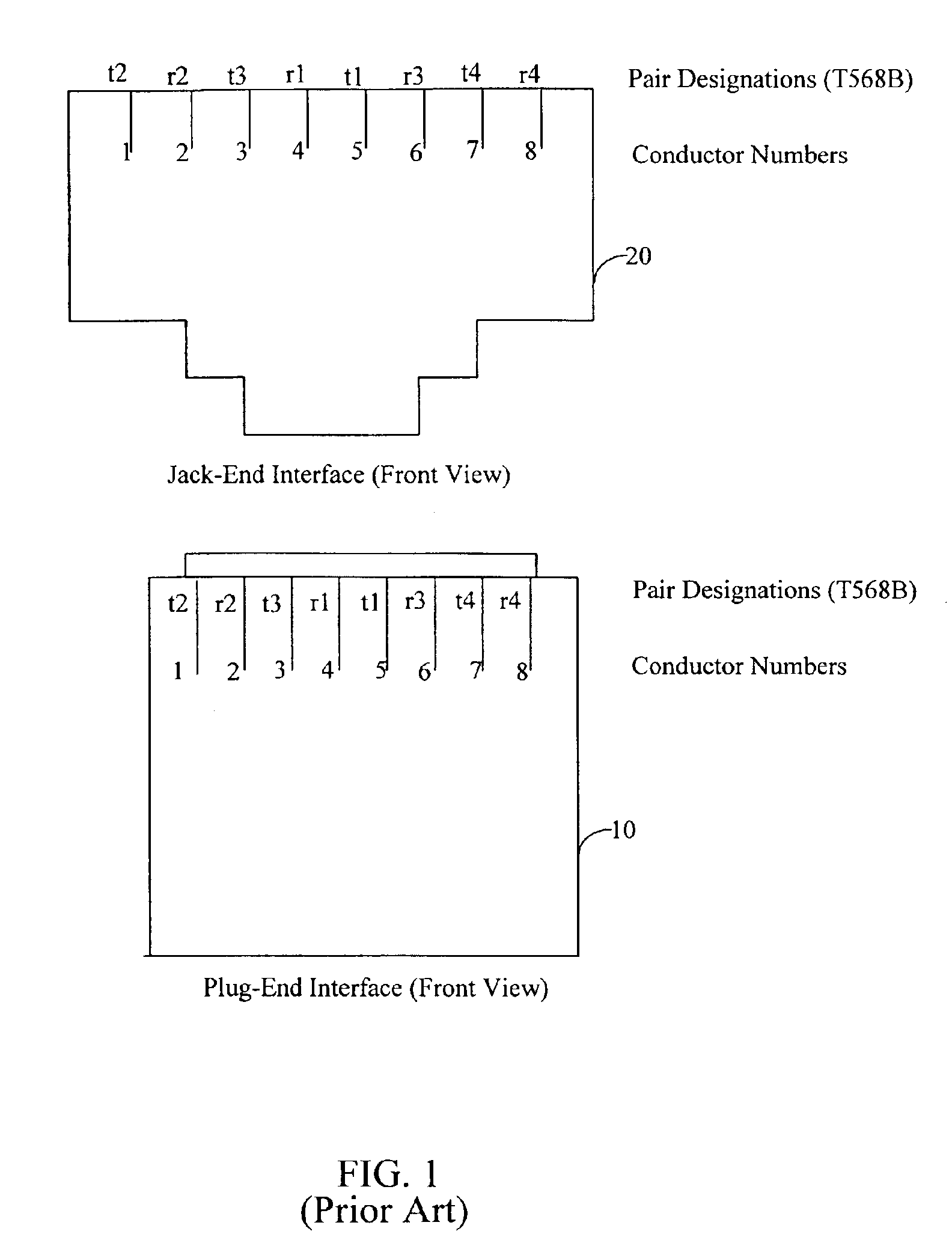
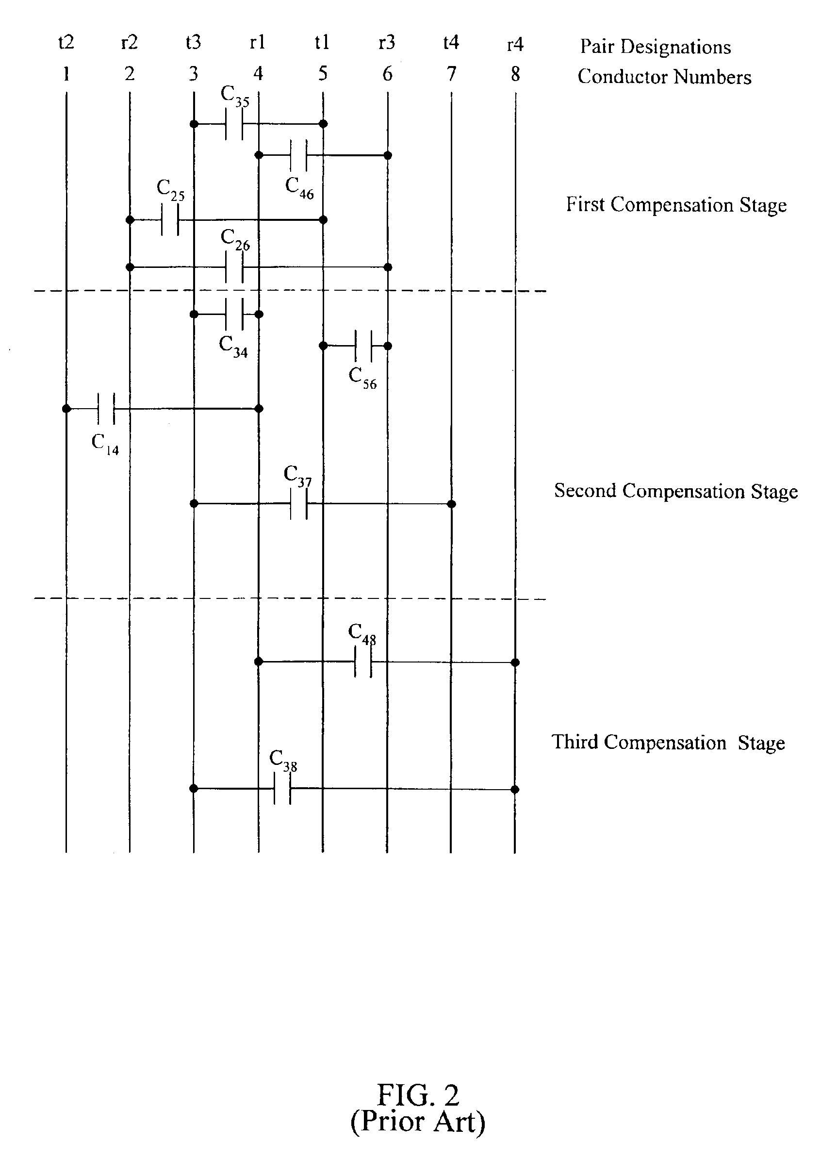
The present invention provides a system and method for compensating for crosstalk balance in a pair combination whose crosstalk balance has been compromised by the deployment of compensation schemes on other pair combinations. FIG. 1 is a schematic drawing representing the wiring scheme for a known modular plug 10 and jack 20 under the TIA T568B specification. Consider, for example, pairs 1 (conductors 4 and 5) and 3 (conductors 3 and 6) in FIG. 1. Although the pair combination is originally balanced, the asymmetric placement of capacitive couplings (not shown) around pairs 1 and 3 at various stages in a multistage compensation scheme for pairs 1&2 and 2&3 on one side and for pairs 1&4 and 3&4 on the other side could cause the crosstalk balance of the pair combination (pairs 1 and 3) to become compromised.

Now consider FIG. 2, which is a schematic drawing representing a known differential-mode to differential-mode crosstalk compensation scheme for a modular plug / jack combination such...


PUM


Abstract

The present invention is directed to a system and method for reducing crosstalk caused by compensation schemes used in a connector to reduce crosstalk. The system provides for balancing crosstalk in an electrical connector having three or more pairs of conductors, wherein two pairs of conductors form a pair combination. The connector also has at least one compensating coupling device connected between conductor pairs of a first pair combination. The compensating coupling device disturbs the crosstalk balance of a second pair combination. The system for balancing crosstalk in the second pair combination includes a corrective coupling device that is connected between the conductor pairs of the second pair combination. In addition, compensating coupling devices in the second pair combination can be adjusted to counteract any crosstalk disturbances caused by the corrective coupling device.

Description

BACKGROUND OF THE INVENTION1. Field of the InventionThe present invention generally relates to electrical connectors, and more particularly, to connectors designed to compensate for crosstalk induced on a conductor pair from other conductor pairs.2. Related ArtIn conventional electrical communication systems, such as these for telephony and data applications, a balanced signal is transmitted over a communication path composed of a pair of conductors that are not grounded. The balanced, or differential, signal constitutes the voltage difference between the individual conductors in the pair without regard to the absolute voltages present on each conductor. In such conductor pair transmission systems, an electromagnetic field is often created that interferes with signals on adjacent conductors. As the frequency of the transmitted signal increases, the effects of this interference become even greater. This interference is electrical noise and is commonly referred to as crosstalk.Crossta...

Claims


Application Information

Patent Timeline
IPC IPC(8): H01R13/66H01R13/719H01R24/00H01R9/22H01R13/646
CPCH01R13/6464Y10S439/941H01R13/646
Inventor HASHIM, AMID I.
Owner COMMSCOPE INC
Learn More