Motorized access apparatus for elevated areas

a motorized access and elevated technology, applied in the field of ladders, can solve the problems of limited load capacity, rare space as desired for such purposes, and the construction of pull-down stairs available in the marketplace is made of wood, and achieves the effect of reliable performan

Inactive Publication Date: 2005-03-15
BATTENBERG WILLIAM D
View PDF14 Cites 33 Cited by
  • Summary
  • Abstract
  • Description
  • Claims
  • Application Information

AI Technical Summary

Benefits of technology

The principal objects and advantages of the present invention include providing a motorized access apparatus; providing such a motorized access apparatus that has ladder sections that slide longitudinally relative to each other during deployment thereof; providing such a motorized access apparatus that includes a motor mechanism that controllably allows gravitational deployment of a ladder means thereof; providing such a motorized access apparatus that requires only approximately eighteen inches of space above an access opening for storage purposes; providing s

Problems solved by technology

Regardless of the amount of space available for storage purposes, rarely is there enough space as desired for such purposes.
Unfortunately, most of the pull-down stairs available in the marketplace are constructed of wood and are limited in load capacity.
As a result, these prior art pull-down stairs are difficult to handle and are somewhat dangerous, particularly for elderly or handicapped users.
Also, if such pull-down stairs are not properly installed such that the joints between the sections of the stairs assume snug abutting engagements therebetween and/or the ends of the bottom section of the stairs are not accurately coped to conform to the underlying floor when the access stairs are pulled down from its s

Method used


Image

  • Motorized access apparatus for elevated areas
  • Motorized access apparatus for elevated areas
  • Motorized access apparatus for elevated areas

Examples


Embodiment Construction

As required, embodiments of the present invention are disclosed herein, however, it is to be understood that the disclosed embodiments are merely exemplary of the invention, which may be embodied in various forms. Therefore, specific structural and functional details disclosed herein are not to be interpreted as limiting, but merely as a basis for claims and as a representative basis for teaching one skilled in the art to variously employ the present invention in virtually any appropriately detailed structure.

This disclosure is a continuation-in-part of U.S. patent application Ser. No. 10 / 670,202 filed Sep. 26, 2003, which disclosure is incorporated herein by reference.

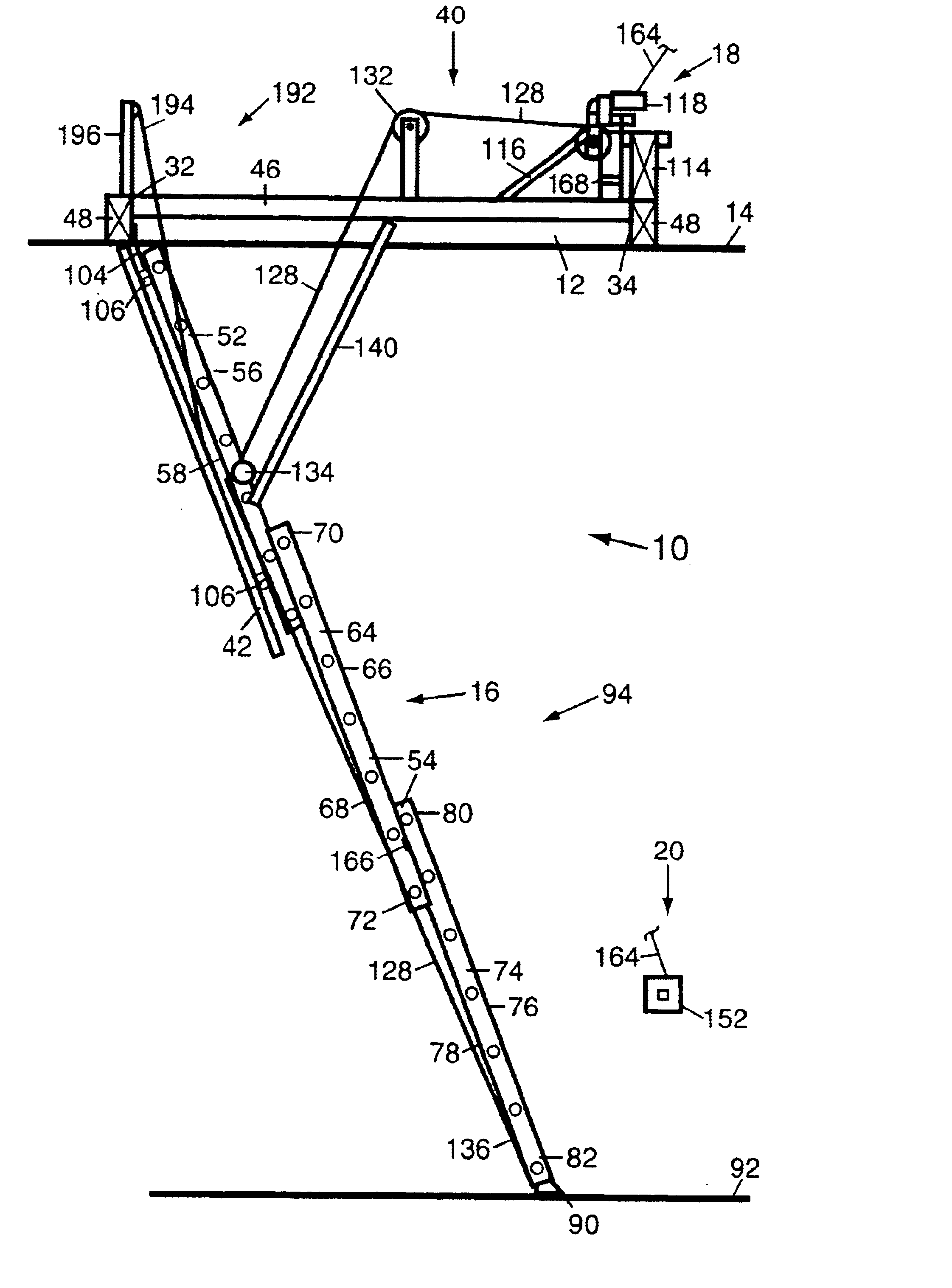
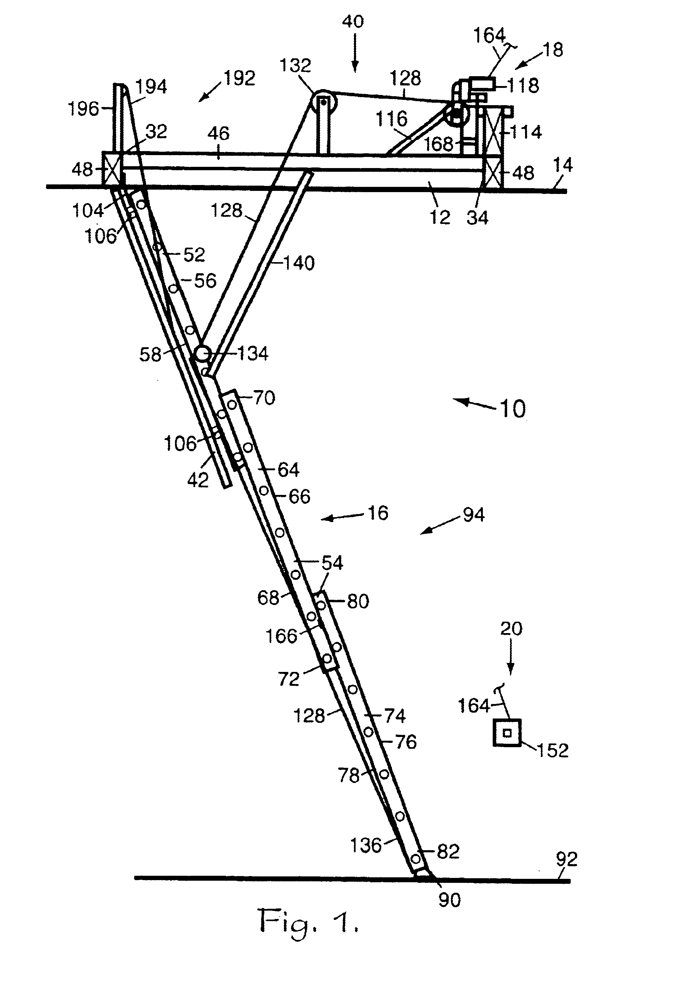
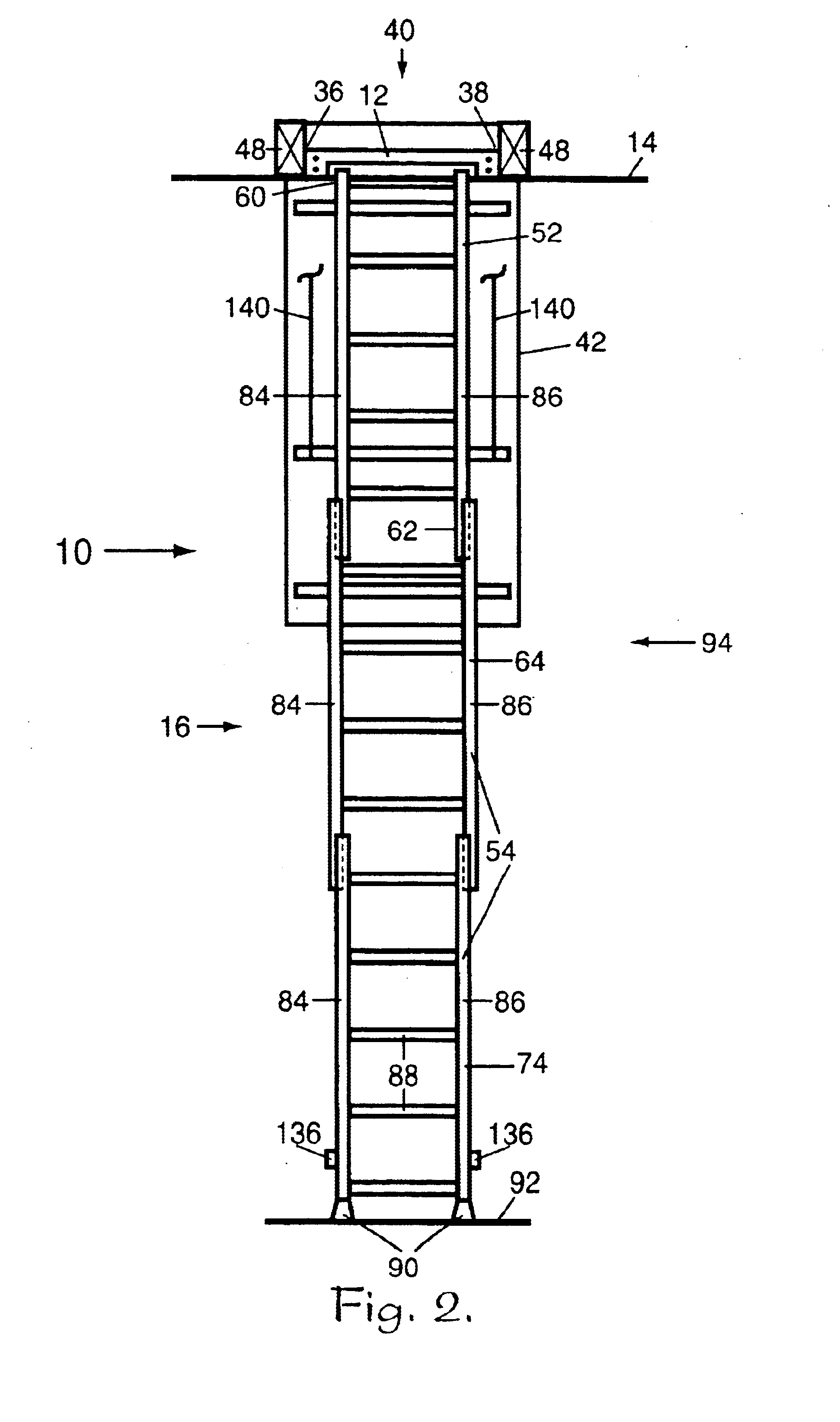
The reference numeral 10 generally refers to a motorized access apparatus for elevated areas in accordance with the present invention, as shown in FIGS. 1 through 5.

The motorized access apparatus 10 includes housing means 12 secured to an elevated structure 14, ladder means 16 pivotally mounted to the housing means 12...


PUM


Abstract

A ladder apparatus for providing access to an area over an elevated structure, the ladder apparatus including a housing secured to the elevated structure; a ladder pivotally mounted to the housing, the ladder means including an upper ladder section and at least one lower ladder section mounted to the upper ladder section; and a motorized deploying mechanism structured to controllably allow the ladder apparatus to be pivotally and gravitationally deployed from a stowed configuration to a partially deployed configuration, controllably allow the at least one lower ladder section to be longitudinally and gravitationally deployed from the partially deployed configuration to a fully deployed configuration, longitudinally retract the at least one lower ladder section from the fully deployed configuration to the partially deployed configuration, and pivotally retract the ladder apparatus from the partially deployed configuration to the stowed configuration. A control mechanism operatively controls the motorized deploying mechanism. A power source provides electrical energy to the motorized deploying mechanism and to the control mechanism.

Description

BACKGROUND OF THE INVENTION1. Field of the InventionThe present invention is related to ladders and, more specifically without limitation, to access ladders.2. Discussion of the Related ArtRegardless of the amount of space available for storage purposes, rarely is there enough space as desired for such purposes. As a result, various means have been developed to utilize otherwise inaccessible space for storage. For example, means such as pull-down stairs have been developed to provide access to space in attics and over garage ceilings. Such spaces generally provide excellent storage for seldom used articles and seasonal items, such as Christmas decorations and the like.Unfortunately, most of the pull-down stairs available in the marketplace are constructed of wood and are limited in load capacity. Such pull-down stairs are generally manually extendable from a folded, storage configuration by pulling on a cord hanging down from one end of the stairs. As a result, these prior art pull-...

Claims


Application Information

Patent Timeline
IPC IPC(8): E04F11/02E04F11/06E06C9/00E06C9/08
CPCE06C9/08E04F11/06E04F11/068
Inventor BATTENBERG, WILLIAM D.
Owner BATTENBERG WILLIAM D
Why Eureka
Try Eureka