
Torque sensor with contoured magnetoelastic element

a magnetoelastic element and torque sensor technology, applied in the field of torque sensors, can solve problems such as difficulty in maintaining during normal operation, and achieve the effect of less sensitive to positional changes

Inactive Publication Date: 2005-03-15
CONTINENTAL AUTOMOTIVE SYST INC
View PDF13 Cites 13 Cited by
  • Summary
  • Abstract
  • Description
  • Claims
  • Application Information

AI Technical Summary

Benefits of technology

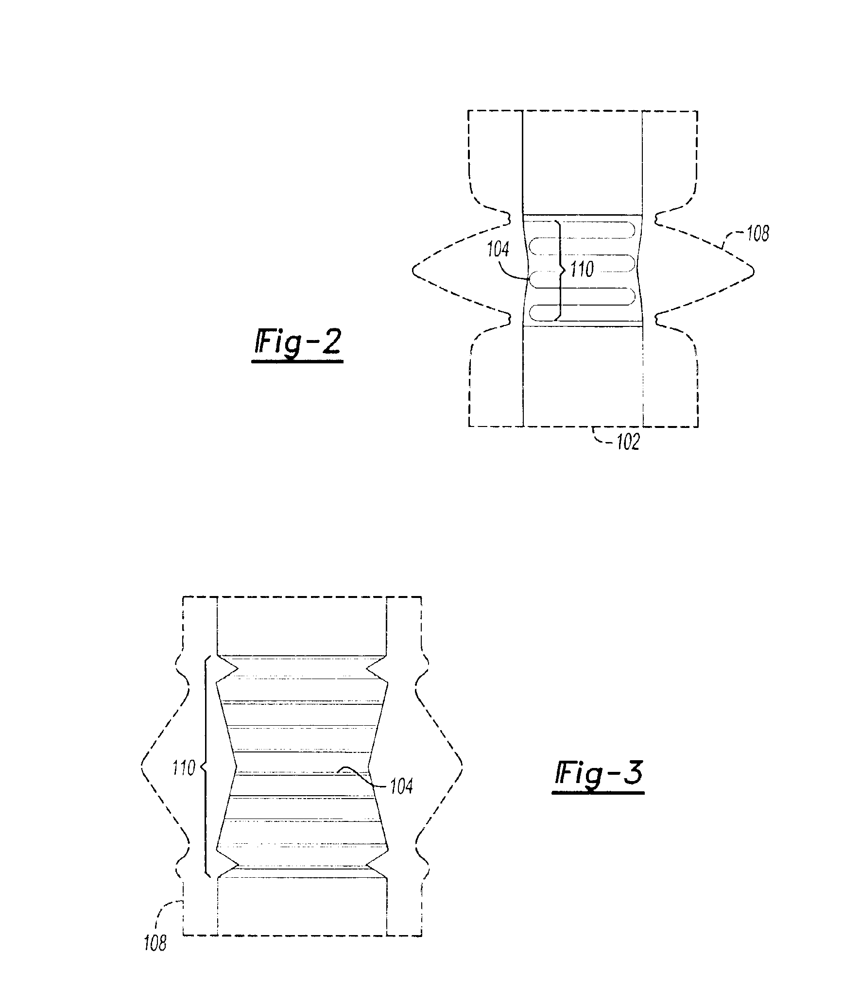
The present invention is about a torque sensor that uses a magnetoelastic element to measure torque. The element is shaped in a way that its magnetic field changes gradually in the axial direction of the shaft, making it less sensitive to positional changes between the element and a magnetometer in the sensor. This helps to accurately measure torque even when the element is deformed through applied torque. The magnetoelastic element is a coating of magnetic material applied to the shaft, which follows its contours and is intimately connected with it, ensuring accurate measurement of shaft deformations.

Problems solved by technology

Normal mechanical mounting tolerances may cause slight axial and / or radial misalignments, however, making the magnetometer sensitive to the relative position of the element and the magnetometer.
Tighter tolerances may help reduce misreadings, but can be difficult to maintain during normal operations.

Method used


Image

  • Torque sensor with contoured magnetoelastic element
  • Torque sensor with contoured magnetoelastic element
  • Torque sensor with contoured magnetoelastic element

Examples


Embodiment Construction

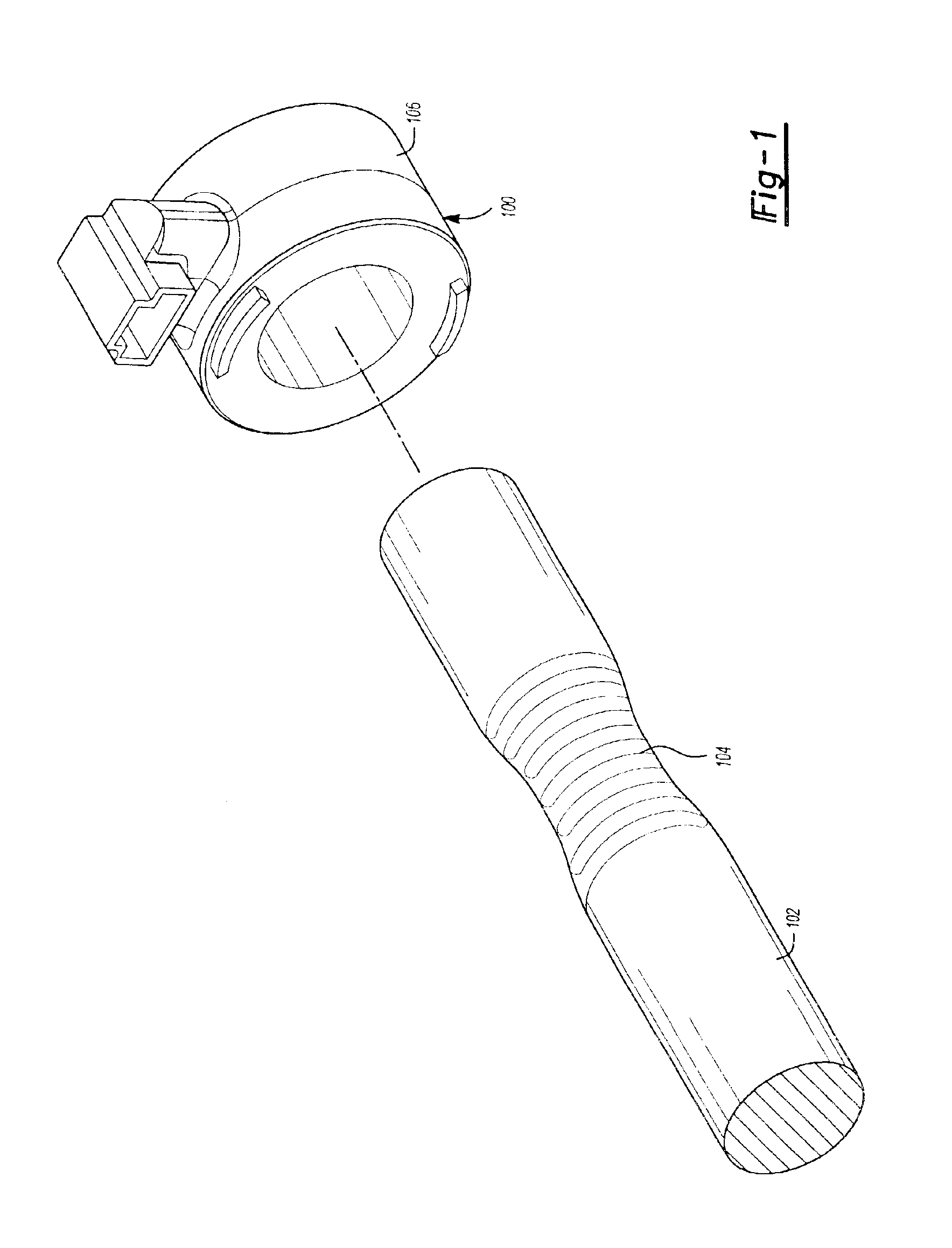
Referring to FIG. 1, a non-compliant magnetoelastic torque sensor 100 measures torque applied to a shaft 102 by sensing magnetic field changes caused by the applied torque. The sensor 100 includes a magnetoelastic element 104 disposed on the shaft 102 and preferably bonded to the shaft 102 so that any torsion force applied to the shaft 102 will also deform the element 104.

More particularly, the element 104 is disposed at a desired location on the shaft 102 and encircles the shaft 102. In one embodiment, the element 104 provides a circumferential magnetic field that has no magnetic polarity in an axial direction if there is no torque applied to the shaft. If torque is applied to the shaft 102, the resulting stress on the magnetic element causes the direction of the magnetic field to change, providing an axial component of the magnetic field corresponding to the amount of torque applied to the shaft 102.

A magnetometer 106 disposed near the element 104 senses the magnetic field change ...


PUM

PropertyMeasurementUnit
torqueaaaaaaaaaa
magnetic fieldaaaaaaaaaa
magnetoelasticaaaaaaaaaa

Abstract

A torque sensor has a contoured magnetoelastic element that generates a magnetic field having a shape that exhibits gradual changes rather than sharp peaks in the axial direction, making the torque sensor less sensitive to positional changes between the magnetoelastic element and a magnetometer in the sensor. The element is contoured in any desired shape to modify the magnetic field generated by the element when it is deformed through applied torque. In one embodiment, the element is a magnetic material coating applied to a contoured shaft.

Description

TECHNICAL FIELDThe present invention is directed to torque sensors, and more particularly to magnetoelastic torque sensors that measure torque in a shaft by monitoring changes in a magnetic field generated by a magnetoelastic element coupled to the shaft.BACKGROUND OF THE INVENTIONTorque sensors known in the art rely on a magnetoelastic element attached to a component to sense torsion forces in the component. Deformation in the component caused by applied torque deforms the magnetoelastic element, resulting in a magnetic field that is proportional to the applied torque. A magnetometer disposed near the element detects the magnitude and polarity of the magnetic field, which indicates the magnitude and polarity of the applied torque.Magnetoelastic elements applied to cylindrical shafts are normally cylindrical as well to accurately reflect any changes in the shaft caused by applied torque. The magnetic field generated by a cylindrical element, however, tends to have a sharp spike at t...

Claims


Application Information

Patent Timeline
Patent Type & Authority Patents(United States)
IPC IPC(8): G01L3/02G01L3/10
CPCG01L3/102
Inventor KILMARTIN, BRIANPSZCZOLA, DAREK
Owner CONTINENTAL AUTOMOTIVE SYST INC
Learn More