
Ballast socket for compact fluorescent lamp

Inactive Publication Date: 2005-03-08
MOON DAI SUNG
View PDF7 Cites 5 Cited by
  • Summary
  • Abstract
  • Description
  • Claims
  • Application Information

AI Technical Summary

Benefits of technology

An object of the present invention is to provide a ballast socket for compact fluorescent lamp capable of enhancing productivity by mounting and manufacturing a printed circuit board, which has various circuit components integrally attached thereon, inside a socket.
Another object of the present invention is to provide a ballast socket for compact fluorescent lamp capable of improving product compatibility by manufacturing the ballast socket of which shape and size are similar to those of a socket for existing incandescent lamp and by making the same possible to be easily installed in an outdoor lamp and an interior lamp including a ceiling lamp, a table lamp, etc.
Further another object of the present invention is to provide a ballast socket for compact fluorescent lamp capable of preventing waste of resources by saving electricity by using a fluorescent lamp consuming electricity correlatively less than an incandescent lamp.
Still another object of the present invention is to provide a ballast socket for compact fluorescent lamp capable of preventing the environmental pollution.
Yet another object of the present invention is to provide a ballast socket for compact fluorescent lamp capable of improving productivity of the lamp by manufacturing the lamp without adhering ballast thereon.

Problems solved by technology

Above all, such conventional lamp is very expensive because the ballast is directly adhered on every lamp, which causes waste of resources and environmental pollution because of being thrown away if the life of the ballast is up.
However, it is difficult to install them in the illuminating means due to a bulky transformer or electronic ballast, which consequently lowers productivity.

Method used


Image

  • Ballast socket for compact fluorescent lamp
  • Ballast socket for compact fluorescent lamp
  • Ballast socket for compact fluorescent lamp

Examples


Embodiment Construction

Reference will now be made in detail to the preferred embodiments of the present invention, examples of which are illustrated in the accompanying drawings.

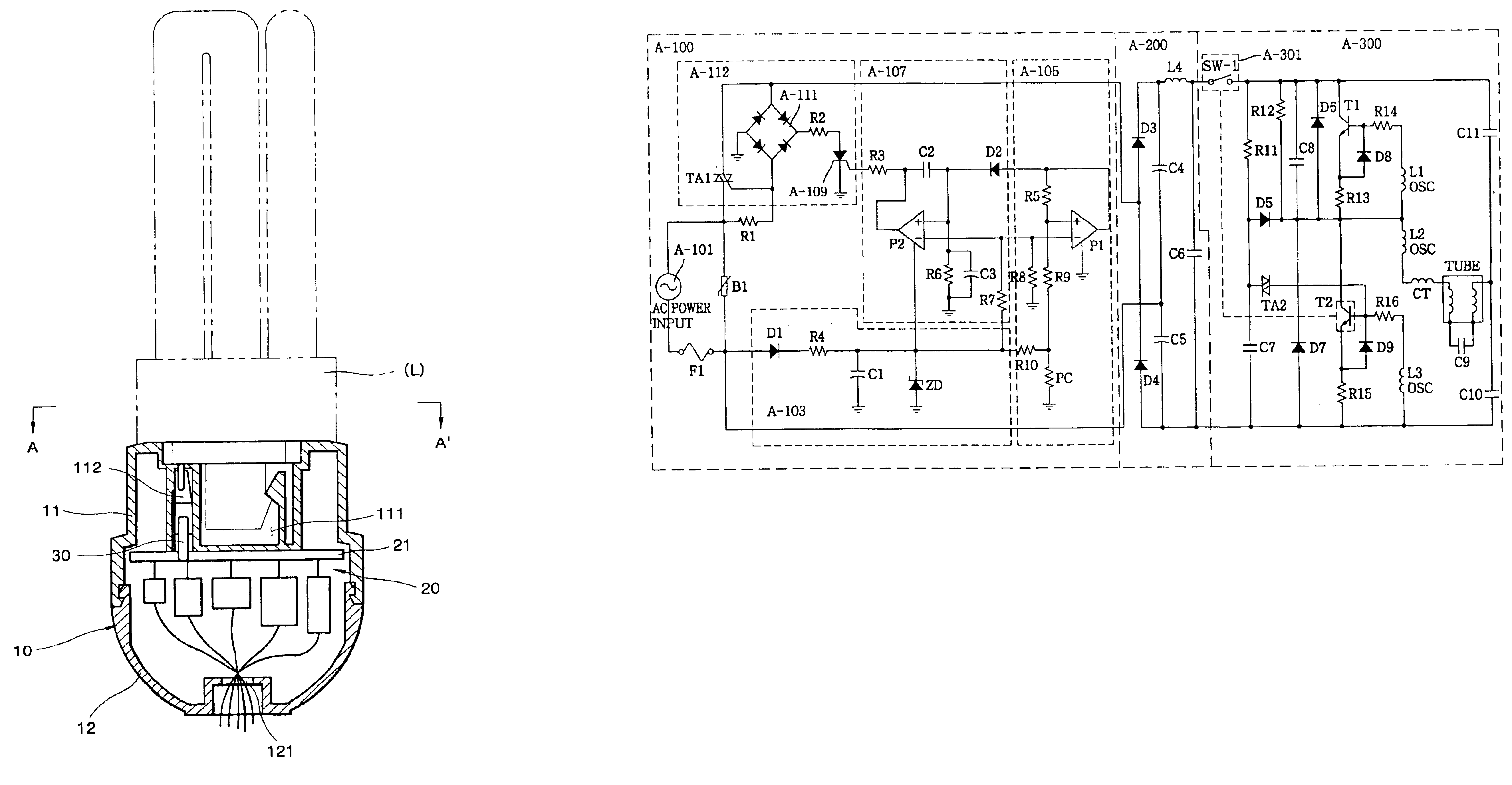
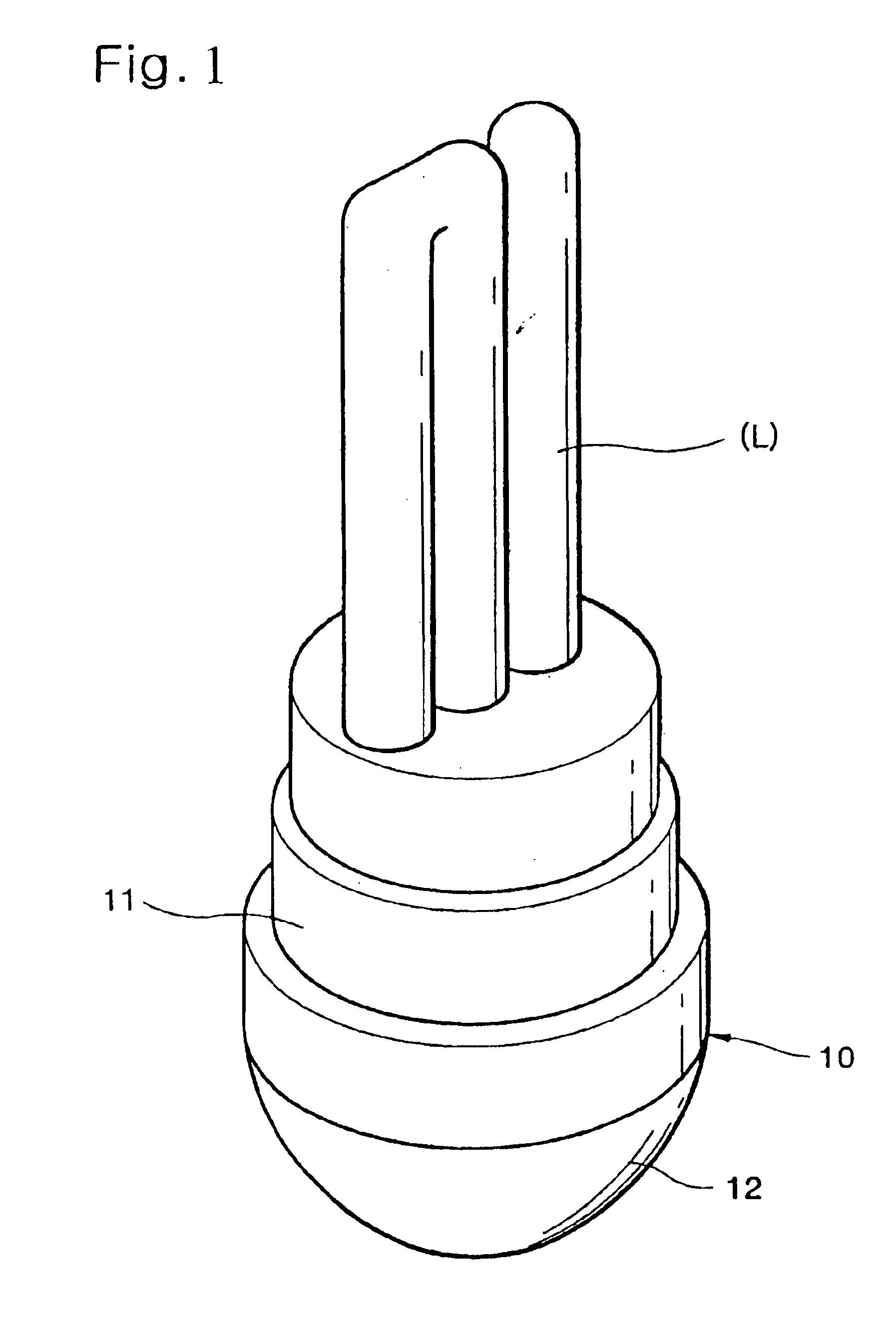
FIG. 1 illustrates a perspective view of a ballast socket applied to the present invention, FIG. 2 illustrates a view of an inside structure of the ballast socket. FIG. 3 illustrates the A-A′ sectional view of FIG. 2, FIG. 4 illustrates a block diagram of the controller structure and FIGS. 5 and 6 illustrate detailed circuit views of a ballast socket according to first and second preferred embodiments of the present invention.

As shown in FIGS. 1 and 2, the socket according to the present invention includes a case 10 having an upper case 11, which has a receiving space 111 for receiving a lamp and a connection terminal 112 connected with the lamp at a side of the receiving space, and a lower case 12, which has a through hole 121 at a lower center of the upper case 11; a controller 20 mounted-in inside of the case 10 for controlling...


PUM


Abstract

A ballast socket for compact fluorescent lamp is disclosed. The ballast socket includes: a case having an upper case, which has a receiving space for receiving a lamp and a connection terminal connected with the lamp at a side of the receiving space, and a lower case, which has a through hole at a lower center of the upper case; a controller mounted inside the case for controlling lighting of the lamp; pins for connecting PCB and the connection terminal; and a printed circuit board on which various circuit components are mounted. The ballast socket looks similar to an incandescent lamp socket in outward form, but the compact fluorescent lamp, which does not have ballast, is used in the ballast socket. Therefore, the ballast socket prevents waste of resources and environmental pollution by saving electricity, and improves productivity of the lamp by manufacturing the lamp not adhering ballast thereon.

Description

BACKGROUND OF THE INVENTION1. Field of the InventionThe present invention relates to a ballast socket for a compact fluorescent lamp, and more particularly, to a ballast socket for a compact fluorescent lamp being enabled to use a compact lamp, which does not have a ballast, regardless of a standard by mounting a printed circuit board (hereinafter, referred to as “PCB”), which has various components attached thereon, inside the socket.2. Background of the Related ArtAs you know, illuminating means, such as incandescent bulbs and lamps, which emits light and is adhered on the ceiling of an office, a house or a building, serves to light up the surroundings or to make dark according to a user's selection when the sun sets or the surroundings get dark and is replaced with a new one if the life of the illuminating means is up.A fluorescent lamp is classified into a 20 W lamp and a 40 W lamp and includes a transformer and ballast.A compact fluorescent lamp, which is conveniently used and ...

Claims


Application Information

Patent Timeline
IPC IPC(8): H05B41/02H05B41/282H05B37/02H05B41/28H05B41/00
CPCH05B37/0218H05B41/02H05B41/282Y02B20/46Y02B20/19H05B47/11Y02B20/00Y02B20/40
Inventor MOON, DAI SUNG
Owner MOON DAI SUNG
Learn More