Safety electrical outlet and switch system

a switch system and electrical outlet technology, applied in the direction of coupling protective earth/shielding arrangement, coupling device connection, contact member penetration/cutting of insulation/cable strand, etc., can solve the problems of electrical wiring construction, unnecessary installation costs, and installation of wall panels

Inactive Publication Date: 2005-03-08
BAUM FAMILY TRUST DTD 1 11 2001 +143
View PDF24 Cites 73 Cited by
  • Summary
  • Abstract
  • Description
  • Claims
  • Application Information

AI Technical Summary

Benefits of technology

The safety electrical outlet and switch system according to the present invention, benefits the electrical contractor in several respects. An aspect of the present invention is an electrical box, a wiring panel installed internally to the box and associated outlet and switch modules which snap into and out of the panel without exposure to or access to electrical system wiring attached behind the panel. The journeyman's work is completed at the rough phase, when installation of the wiring panel is complete. Thus, there is no need for the journeyman to return to the job site during the makeup phase because any semi-skilled laborer, following a punch-out code or other indicator on the panel, can snap-in an appropriate outlet or switch module. Further, there is no wiring access after the rough phase, protecting wiring integrity. Also, there are no exposed conductors or parts inside the electrical box that can be inadvertently damaged during wall panel installation. A protective cover is provided that prevents fouling by drywall compound or other materials during the makeup phase.
Yet another aspect of the present invention is a method of installing an electrical box having an open front face. The method comprises the steps of attaching a box mount to a wall stud so that an alignment guide of the box mount matches a wall stud edge and mounting the electrical box onto the box mount so that the electrical box slides relative to the box mount in a direction generally perpendicular to the wall stud. The method comprises the further steps of locating a plurality of fixed positions for the electrical box along said box mount and latching the box in one of the positions so as to accommodate the thickness of a wall panel installed on the wall stud. Each of the positions provides a specific distance between the front face and the alignment guide.

Problems solved by technology

Problems with Standard Wiring Construction
There are multiple problems with standard electrical wiring construction.
From the electrical contractor perspective, there are unnecessary costs associated with installation.
During the makeup phase, installation of the wall panels can damage the work completed during the rough phase.
One way in which damage occurs is router contact with exposed cables when drywallers create a hole to accommodate electrical box openings.
Another form of damage occurs when drywall compound or paint fouls the exposed cables, insulation and labeling.
From the general contractor perspective, there are other problems with the standard electrical wiring construction.
Verification of the electrical contractor's work is not possible until after the makeup phase.
After the makeup phase, however, miswiring typically requires cutouts in the installed wall panels and associated patches after corrections are completed.
Further, the electrical system cannot be activated until after verification.
Thus, during the rough and makeup phases, electricity for tools and lighting must be supplied by generators, which create hazards due to fumes, fuel, and noise and are an unreliable electrical source.
In addition, until the trim phase is completed, unskilled personnel have access to the electrical cable.
Tampering can comprise the integrity of the electrical wiring and also create a safety problem after power is activated.

Method used


Image

  • Safety electrical outlet and switch system
  • Safety electrical outlet and switch system
  • Safety electrical outlet and switch system

Examples


Embodiment Construction

System Overview

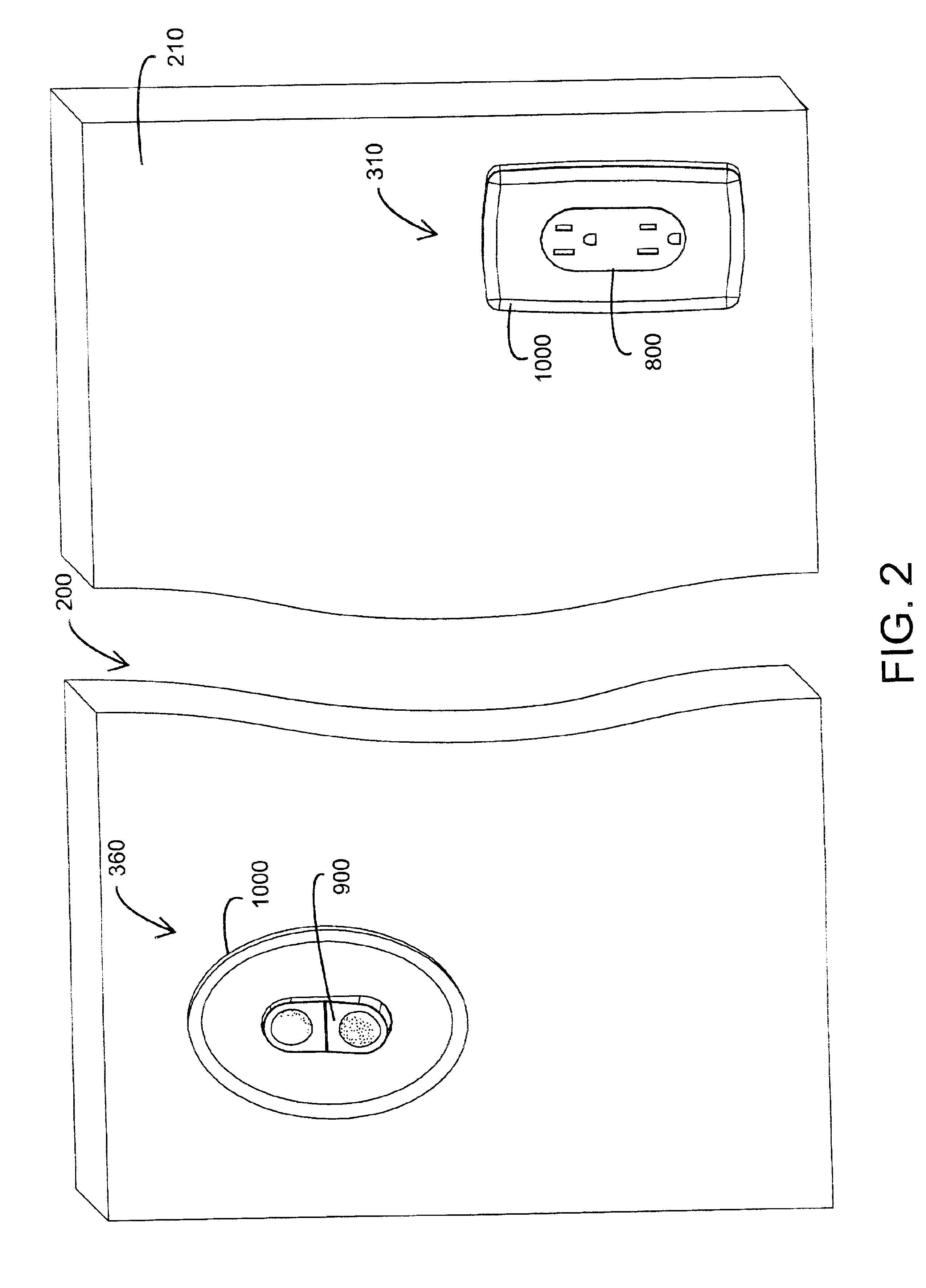
FIG. 2 illustrates one embodiment of an installed safety electrical outlet and switch system 200 according to the present invention. As shown in FIG. 2, the outlet and switch system 200 comprises a outlet assembly 310 and a switch assembly 360. Each of these assemblies 310, 360 provide a user-accessible electrical function. The outlet assembly 310 is mounted in a wall 210 and functions to supply a user with electrical power through a conventional AC plug inserted into an outlet module 800. The switch assembly 360 is also mounted in the wall 210 and functions to allow a user to control electrical power to an outlet, a light or any of various electrical devices (not shown) by actuating a switch module 900. The installed outlet assembly 310 includes a face plate 1000 and an outlet module 800 mounted so that its visible portion is generally flush with the face plate 1000. The installed switch assembly 360 includes a face plate 1000 and a switch module 900 mounted so that ...


PUM

PropertyMeasurementUnit
Poweraaaaaaaaaa

Abstract

An electrical wiring assembly comprises a wiring panel and an electrical module. The wiring panel has a front side and a back side and is installable within an electrical box. The electrical module has a front cover and a back cover, and the front cover provides a user accessible electrical function. Panel fixtures extend generally perpendicularly from the front side of the wiring panel and shield panel contacts. Breakaways are configured to be removable so as to isolate a first portion of the panel contacts from a second portion of the panel contacts. Module fixture extend generally perpendicularly from the back cover of the electrical module and shield module contacts. The module fixtures are configured to engage the panel fixtures so as to electrically connect the module contacts with the panel contacts.

Description

BACKGROUND OF THE INVENTIONInstallation of a standard AC electrical system in a new residence or commercial site occurs in three phases, corresponding to the building construction. The rough phase corresponds to rough framing of the building, prior to attachment of wall panels to the frame. During this phase, blue boxes or similar electrical boxes are mounted to wall studs at predetermined locations, so that outlets are 18″ and switches are 36″ from the floor. Various box types are available, such as single-, double-, triple- or quadruple-wide configurations, among others. After the boxes are installed, a journeyman electrician, following a predetermined layout, routes Romex® brand or equivalent power cables through the framing to the appropriate boxes. A typical power cable has two solid core insulated conductors and a ground conductor, all surrounded by a non-metallic sheath. The power cable is fed through openings in the rear or sides of the electrical boxes. The journeyman typic...

Claims


Application Information

Patent Timeline
IPC IPC(8): H01R25/00H01R13/70H01R13/60H02B1/01H02G3/00H02G3/08
CPCH01R13/652H01R24/78H01R13/70Y10T29/49169H01R2103/00Y10T29/49128H01R25/006
Inventor GORMAN, MICHAEL P.
Owner BAUM FAMILY TRUST DTD 1 11 2001
Why Eureka
Try Eureka