Eureka AIR delivers breakthrough ideas for toughest innovation challenges, trusted by R&D personnel around the world.

Locking container

a container and locking technology, applied in the field of childproof locking containers and locking containers, can solve problems such as difficulty in securing with childproof locks

Inactive Publication Date: 2005-03-08
MEADWESTVACO CORP
View PDF19 Cites 128 Cited by
  • Summary
  • Abstract
  • Description
  • Claims
  • Application Information

AI Technical Summary

Benefits of technology

In one preferred embodiment of the invention, the tray is rectangular and has a central main body, rectangular opposite sidewalls and rectangular opposite end walls. Preferably, the cover is a paperboard or plastic material, which is formed in three parts by providing two parallel creases. A base panel underlies the tray and is glued or otherwise connected to the bottom of the tray. A spine panel overlies an end of the tray, and a cover panel overlies the top of the tray. The cover panel may be folded at a free end and laminated to provide a relatively rigid cover. Alternatively, a second layer may be laminated on the inside of the cover panel to provide rigidity and also to provide holders for the protected contents of the package.
To release the latch extension, a pull ring on an opposite end of the lock strap is moved in a direction away from the locking position. Stops prevent excessive movement in the unlocking direction. Movement of the lock strap to the unlocking position releases the lock flap for opening. The flexible straps return the lock strap to the locking position when the pull ring is released.
The cover is then returned to the closed position. Pushing downward on a center of the cover panel resiliently bends the cover about a longitudinal axis, permitting edges of the cover panel to snap beneath the inward projections on the upward extended sides of the tray. The lock flap is then closed on the cover. The latch extension rib extends through the opening in the cover and the aligned opening in the shelf portion of the tray. The latch extension rib has a sloped outward surface, which engages a sloped camming surface on the top of the lock rib, pushing the lock rib and the lock strap away from the locking position so that the latch extension rib may snap beneath the lock rib. The flexible straps return the lock strap and the lock rib to the locking position, and the package is secure against unintended opening.

Problems solved by technology

Many medicines are packaged in flat boxes, which are difficult to secure with childproof locks.

Method used


Image

  • Locking container
  • Locking container
  • Locking container

Examples


Embodiment Construction

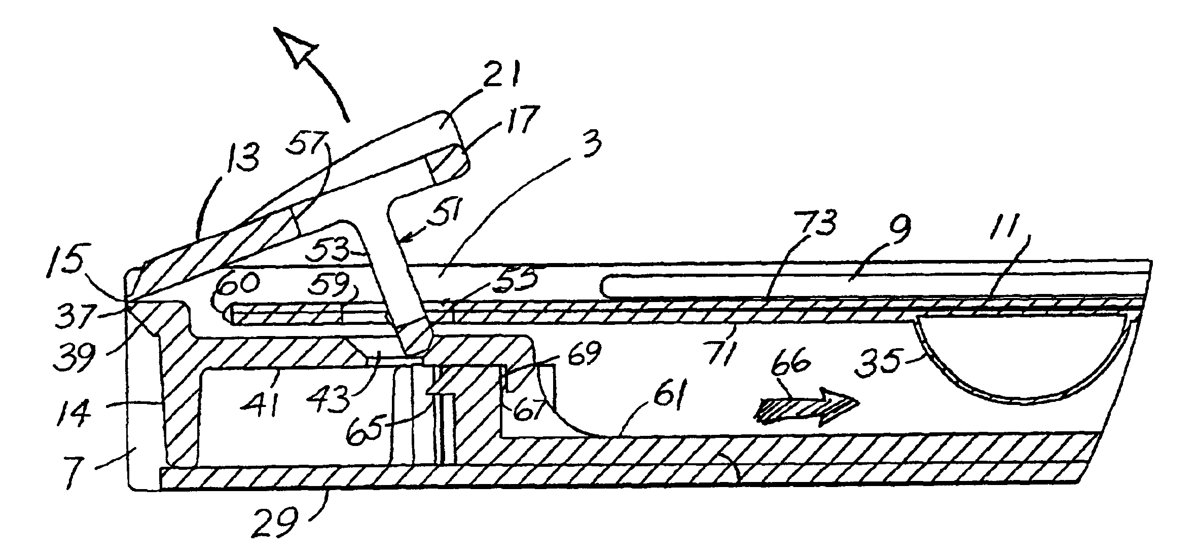
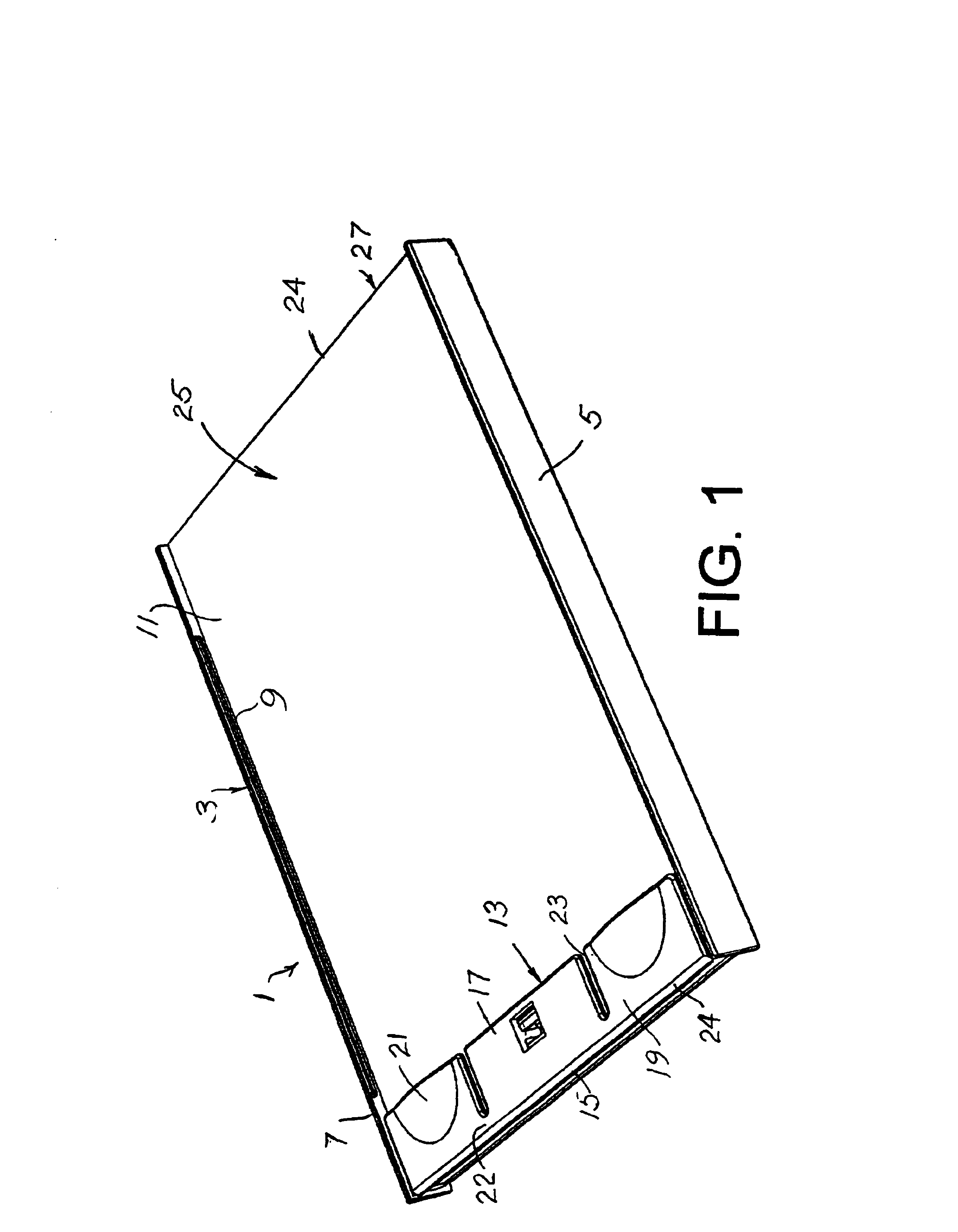
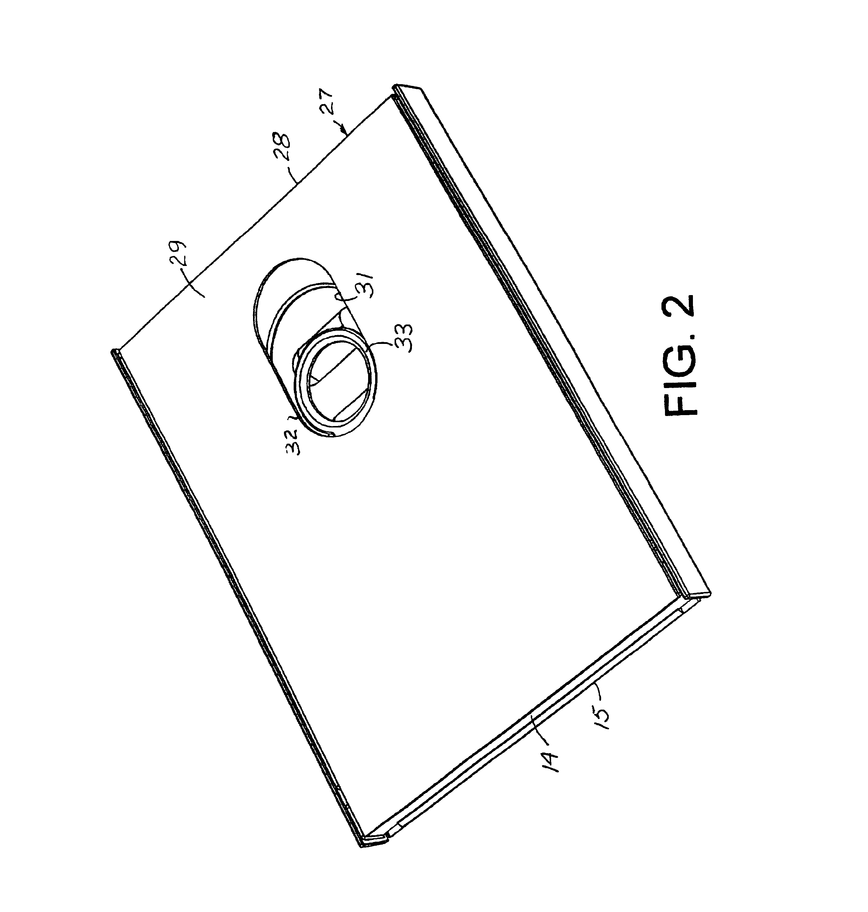
Referring to FIG. 1, a locking container for holding pills or other objects is generally indicated by the numeral 1. The container has a rectangular molded plastic tray 3 with rectangular opposite lateral sides 5 and 7. Elongated ledges 9 extend inward from upper edges of the sides 5 and 7. The ledges hold down side edges of a cover panel 11. The cover is formed as a rigid section of a creased and folded plastic or paperboard sheet material enclosure 25.

A locking flap 13 holds down one end of the cover panel 11. The locking flap is connected to an upper edge of longitudinal end 14 of the tray 3 by a living hinge 15. The locking flap has an operative center section 17 and two side sections 19. The center section has a latch extension. The side sections have raised curved portions 21, under which tips of two fingers may be inserted for lifting the entire flap 13. The center section 17 and the two side sections 19 are separated by grooves 23. The grooves prevent raising of the center s...


PUM


Abstract

A locking container has a tray with sidewalls, a shelf and a bottom with an elongated opening. A sliding lock and a spring are formed in the bottom opening. A lock flap is hinged to the shelf. A cover has a base glued to the tray bottom, a spine end and a top panel. A latch extension extends form the flap through holes in the shelf and top panel. Sliding the lock with a finger or thumb and lifting with fingers both side sections of the flap releases the latch extension and allows raising of the top panel. Articles are held in bubbles of an inner laminate on the panel.

Description

BACKGROUND OF THE INVENTIONLocking containers, especially childproof locking containers, in which multiple movements must be applied to open the container, have many uses. One use for locking containers is medicine containers. Locking caps on medicine bottles are well known. The caps usually require axial pressure or inward radial squeezing while turning the caps to remove the caps from the containers and to provide access to medicine therein.Many medicines are packaged in flat boxes, which are difficult to secure with childproof locks. Needs exist for flat boxes that have locks which require multiple motions for opening. Needs exist for inexpensive locking boxes.SUMMARY OF THE INVENTIONThe invention provides a locking container. In a preferred form of the invention the locking container is flat and has one element, which provides a form and a lock, and a second element, which provides an enclosure. Preferably the enclosure also includes a carrier for the protected contents of the c...

Claims


Application Information

Patent Timeline
IPC IPC(8): B65D83/04B65D50/00B65D50/04
CPCB65D50/045B65D83/0463B65D2251/1025B65D2215/02Y10T292/432
Inventor GELARDI, JOHN A.
Owner MEADWESTVACO CORP
Why Eureka
Eureka Blog
Learn More