Compact optical package with modular optical connector

Inactive Publication Date: 2005-03-01
INTEL CORP
View PDF23 Cites 12 Cited by
  • Summary
  • Abstract
  • Description
  • Claims
  • Application Information

AI Technical Summary

Benefits of technology

Because the optical fibers 14 are so fragile handling of the optical component 5 must be done very carefully, and it is difficult to automate manufacturing processes without harm to the optical fibers. Additionally, shipping of the optical component is expensive since extra protective precautions are used to ensure that the optical component 5 including the optical fibers 14 is not damaged during transit. This usually entails using large boxes that allow the optical fibers 14 to be coiled in circles with a large radius, and padding the optical fibers 14 and connectors 12.

Problems solved by technology

Such devices formed with optical fibers would typically be much larger or would not be feasible at all.
A disadvantage of the multiple connectors 12 is that the time to connect each of the connectors 12 may be significant.
Because this process is not easily automated, the amount of time for connecting and disconnecting optical components, e.g., for testing, may be significant.
The optical fibers 14 are fragile, and may be easily damaged.
Because the optical fibers 14 are so fragile handling of the optical component 5 must be done very carefully, and it is difficult to automate manufacturing processes without harm to the optical fibers.
Additionally, shipping of the optical component is expensive since extra protective precautions are used to ensure that the optical component 5 including the optical fibers 14 is not damaged during transit.

Method used


Image

  • Compact optical package with modular optical connector
  • Compact optical package with modular optical connector
  • Compact optical package with modular optical connector

Examples


Embodiment Construction

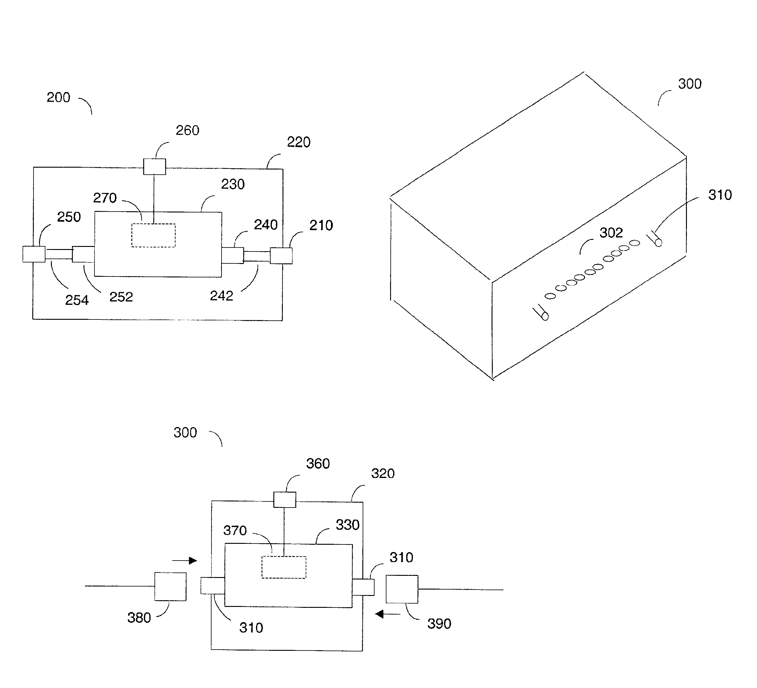
An optical component has a package casing with an integrated modular optical connector. The modular optical connector allows for quick and easy coupling of the optical component to multiple optical waveguides. Because the optical component does not have fragile, long, exposed optical fibers, automation equipment may be used in the manufacture, handling, and testing of the optical component. Shipping costs are reduced by allowing smaller packaging with less protective material. Additionally, it is much quicker to hook up the optical component by using a modular connector than by connecting the individual connectors 12 of FIG. 1.

FIG. 3 is a schematic diagram that shows an embodiment of an optical component 200 having a modular optical connector 210 that is integrated into the package casing 220 of the optical component 200. The optical component 200 comprises an optical circuit 230 enclosed within the package casing 220. The optical circuit 230 may be any of various optical devices, s...


PUM


Abstract

An optical connector comprises an optical circuit and a package casing. The package casing has an integrated modular optical connector, which has multiple optical waveguides.

Description

BACKGROUND OF THE INVENTION1. Field of the InventionThe described invention relates to the field of optical circuits. In particular, the invention relates to an optical circuit package having a modular optical connector.2. Description of Related ArtOptical circuits include, but are not limited to, light sources, detectors and waveguides that provide such functions as splitting, coupling, combining, multiplexing, demultiplexing and / or switching. Planar lightwave circuits (PLCS) are optical circuits that are manufactured and operate in the plane of a wafer. PLC technology is advantageous because it can be used to form many different types of optical devices, such as array waveguide grating (AWG) filters, optical add / drop (de)multiplexers, optical switches, as well as hybrid opto-electronic integrated devices. Such devices formed with optical fibers would typically be much larger or would not be feasible at all. Further, PLC structures may be mass produced on a silicon wafer.FIG. 1 is ...

Claims


Application Information

Patent Timeline
IPC IPC(8): G02B6/30G02B6/12G02B6/38G02B6/42G02B6/34
CPCG02B6/30G02B6/12009G02B2006/12135G02B6/4201G02B6/3814G02B6/4271
Inventor VODRAHALLI, NAGESH K.SAMBYAL, JAIOM S.SUR, BISWAJIT
Owner INTEL CORP
Why Eureka
Try Eureka