Forehead support for facial mask
a technology for facial masks and support points, which is applied in breathing masks, breathing protection, other medical devices, etc., can solve the problems of affecting the wearer's nose, affecting the wearer's facial mask, and compressing the mask against the wearer's fa
- Summary
- Abstract
- Description
- Claims
- Application Information
AI Technical Summary
Benefits of technology
Problems solved by technology
Method used
Image
Examples
first embodiment
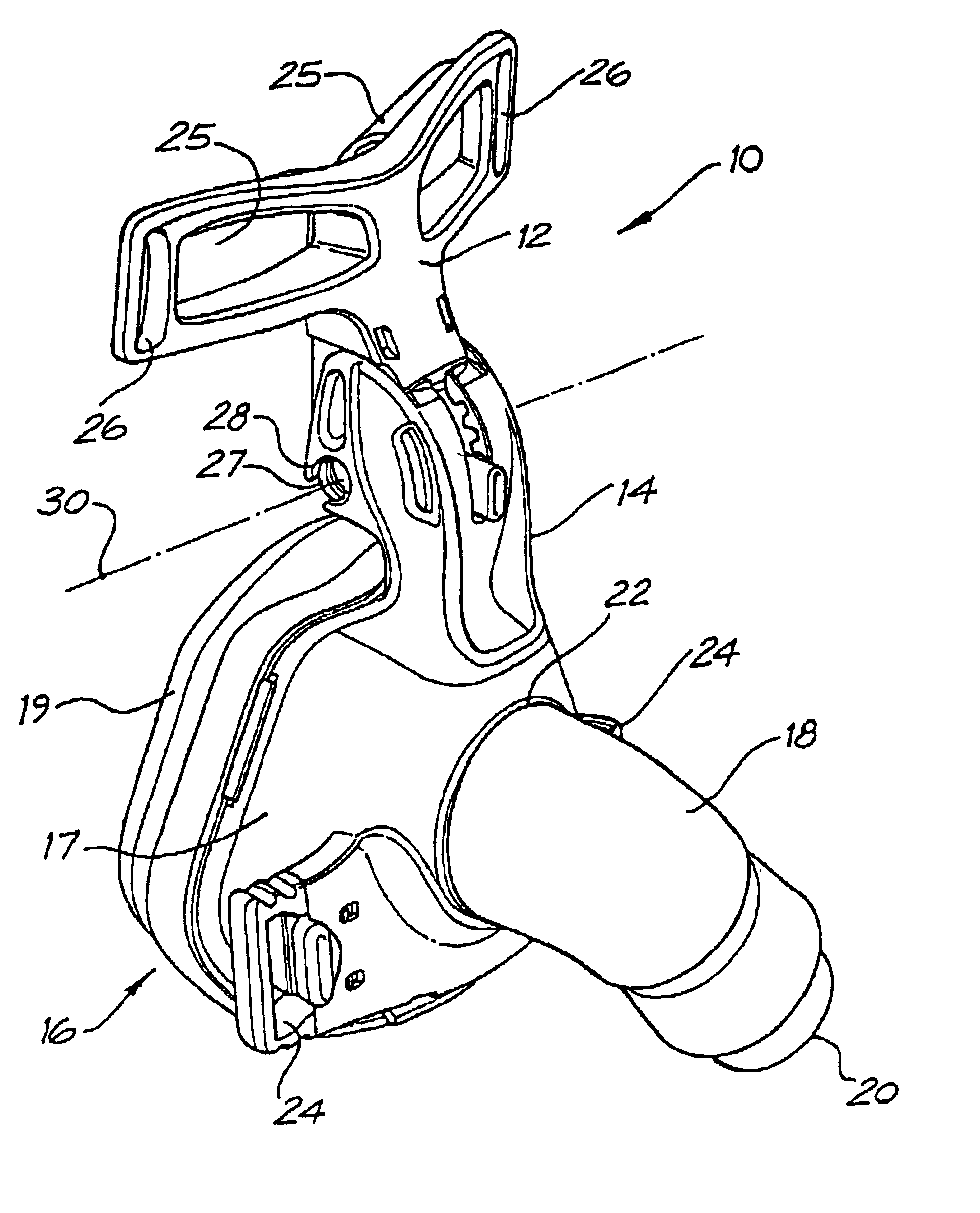
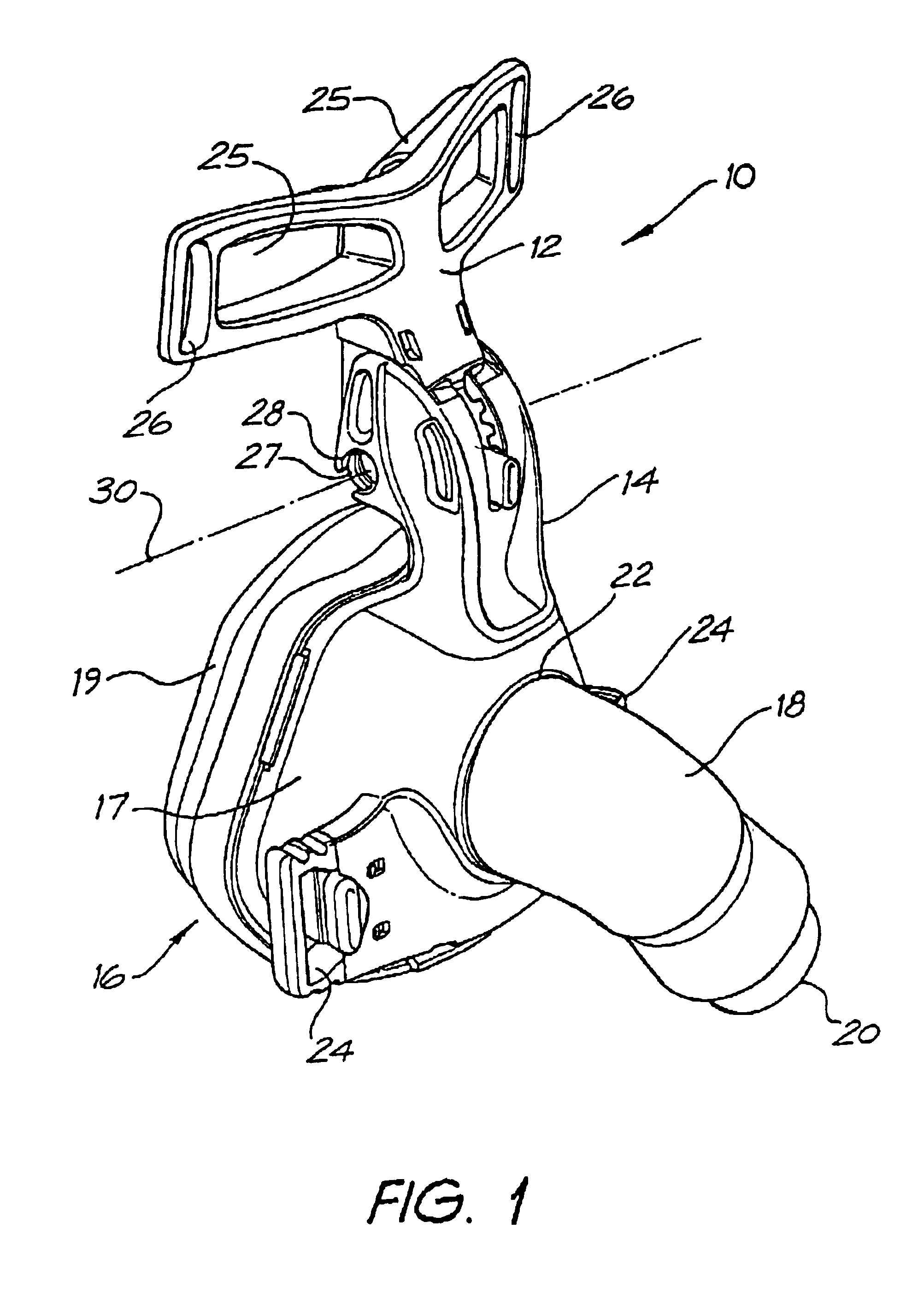
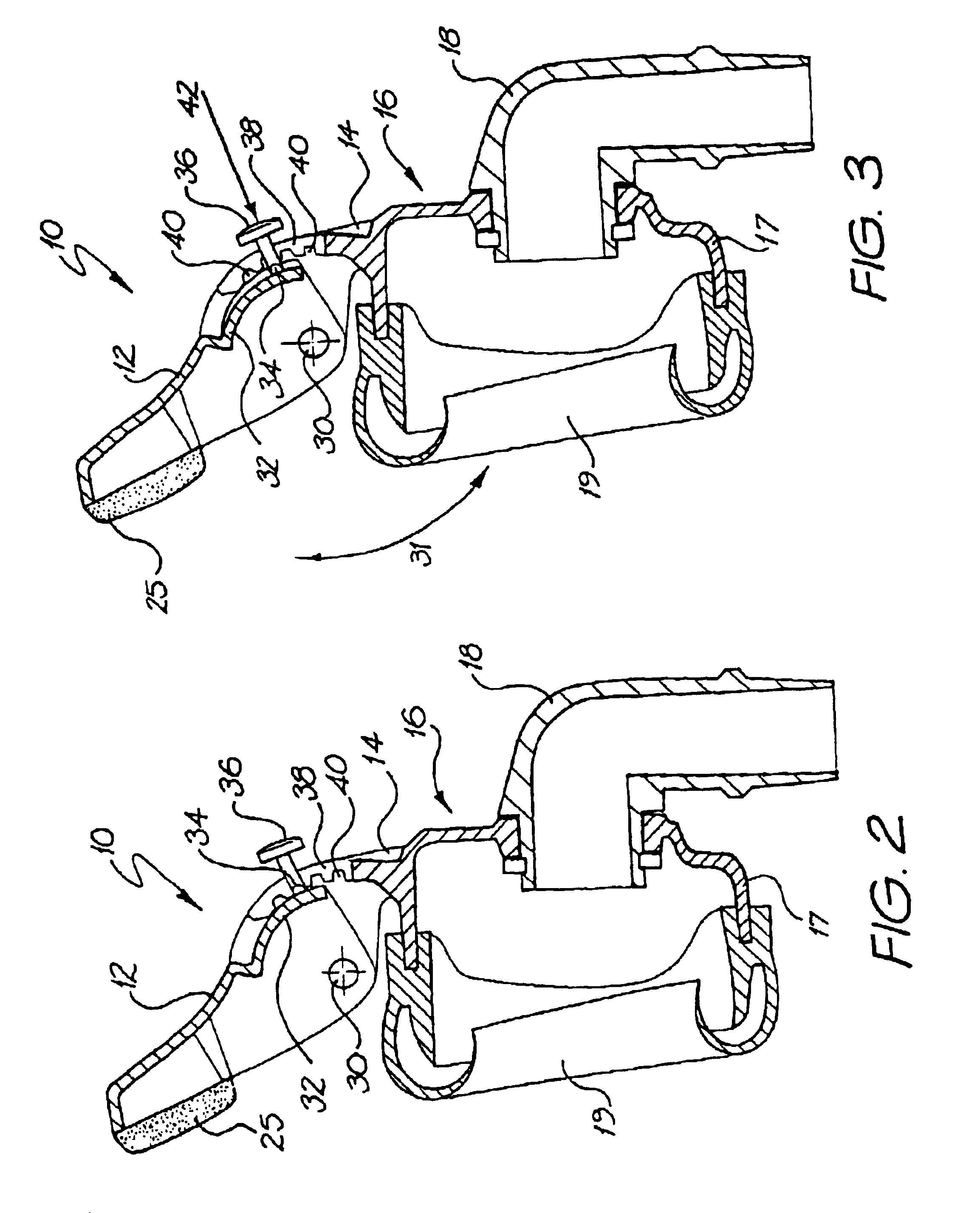
FIG. 1 shows a forehead support 10 according to the present invention. The forehead support 10 includes a generally T-shaped cushion frame 12 pivotally mounted to a joining member 14. The joining member 14 is connected to a nasal respiratory mask 16 used to supply breathable gas to a wearer's airways.
The mask 16 includes a mask shell 17 and a mask cushion 19. The mask shell 17 also includes an angled connector 18 which has a distal end 20 for connection to a gas supply conduit (not shown) and a proximal end 22 for connection to the mask 16. The connector 18 communicates the supplied gas from the gas supply conduit to the interior of the mask 16. The mask shell 17 also includes a pair of slotted connectors 24 to which are respectively connected ends of a lower head strap (not shown) for securing the nasal mask to the wearer's head.
The joining member 14 is connected on top of the mask shell 17 generally adjacent and above the wearer's nose. It will be appreciated that the nasal mask 1...
second embodiment
In the second embodiment, their are two buttons 36. Pressing the buttons together in the direction of arrows 52 flexes the tongues 34 towards each other to disengage them from the grooves 40 and allow angular adjustment between the cushion frame 12 and the joining member 14. Releasing the buttons 36 allows the tongues 34 to resiliently flex towards, and into engagement with, the grooves 40 to lock the cushion frame 12 and the joining member 14 against relative pivotal movement.
FIGS. 9 to 14 show a third embodiment of a forehead support 60 according to the present invention. Like reference to those used in describing the first embodiment will also be used to denote like features in relation to the third embodiment.
third embodiment
In the third embodiment, the cushion frame 12 is integrally moulded with the joining member 14 and joined by an integral hinge 62 (sometimes known as a natural or living hinge). The cushion frame 12 and the joining member 14 can be pivotted relative to each other about the hinge 62. The forehead support 60 is moulded in a substantially ‘flat’ configuration, as shown in FIG. 9. The cushion frame 12 is then pivotted through approximately 180° relative to the joining member 14 until the tongue 34 engages one of the four grooves 40. As with the earlier embodiments, pressing the button 36 in the direction of arrow 42 frees the tongue 34 from engagement with the grooves to allow adjustment of the angle between the cushion frame 12 and the joining member 14. The button 36 and the tongue 34 are inherently biased to a position engaging one of the grooves 40, again consistent with earlier embodiments.
In the preferred form shown, the mask shell 17 is also integrally formed with the joining mem...
PUM
 Abstract
Description
Claims
Application Information
 - R&D
- Intellectual Property
- Life Sciences
- Materials
- Tech Scout
- Unparalleled Data Quality
- Higher Quality Content
- 60% Fewer Hallucinations
Browse by: Latest US Patents, China's latest patents, Technical Efficacy Thesaurus, Application Domain, Technology Topic, Popular Technical Reports.
© 2025 PatSnap. All rights reserved.Legal|Privacy policy|Modern Slavery Act Transparency Statement|Sitemap|About US| Contact US: help@patsnap.com


