
Automated dense phase fluid cleaning system

Inactive Publication Date: 2005-02-22
EKC TECH
View PDF7 Cites 7 Cited by
  • Summary
  • Abstract
  • Description
  • Claims
  • Application Information

AI Technical Summary

Benefits of technology

Accordingly, the invention more efficiently and effectively removes contaminants from the substrate. In addition, the invention automatically accounts for the variations of each substrate, in real time.

Problems solved by technology

These conventional solvent aided cleaning processes are currently being re-evaluated due to environmental concerns.
In addition, recent environmental legislation mandates that many of the organic solvents used in wet processes be banned or their use severely limited.
However, such processes often leave a residue after dry cleaning, which is unacceptable because such residue may cause device failures or limit operation efficiency.
Accordingly, it is difficult to determine the optimal process parameters for cleaning.
Therefore, there are generally no ultimate predefined process parameters that can accurately account for all substrates to remove all contaminants.

Method used


Image

  • Automated dense phase fluid cleaning system
  • Automated dense phase fluid cleaning system
  • Automated dense phase fluid cleaning system

Examples


Embodiment Construction

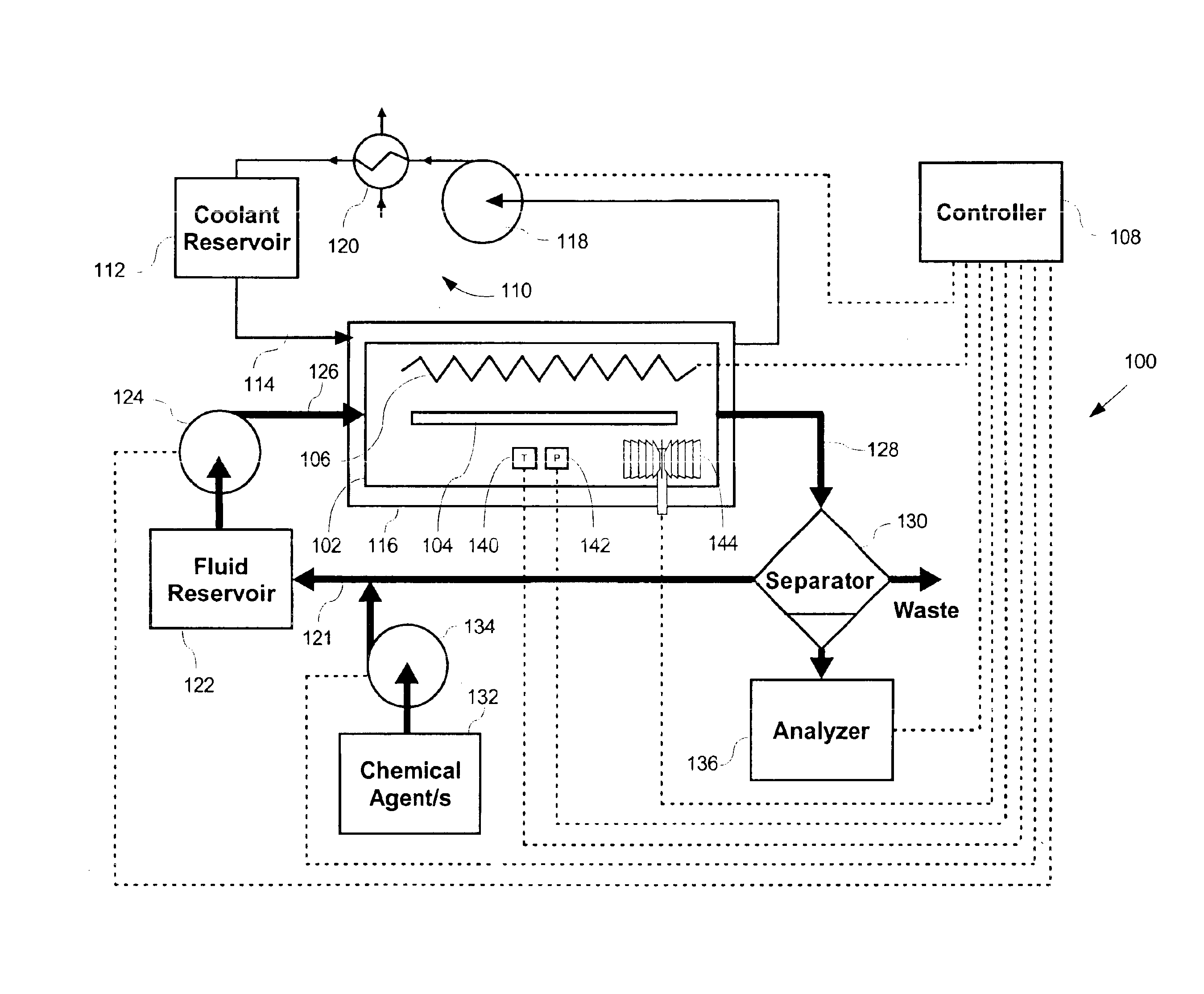
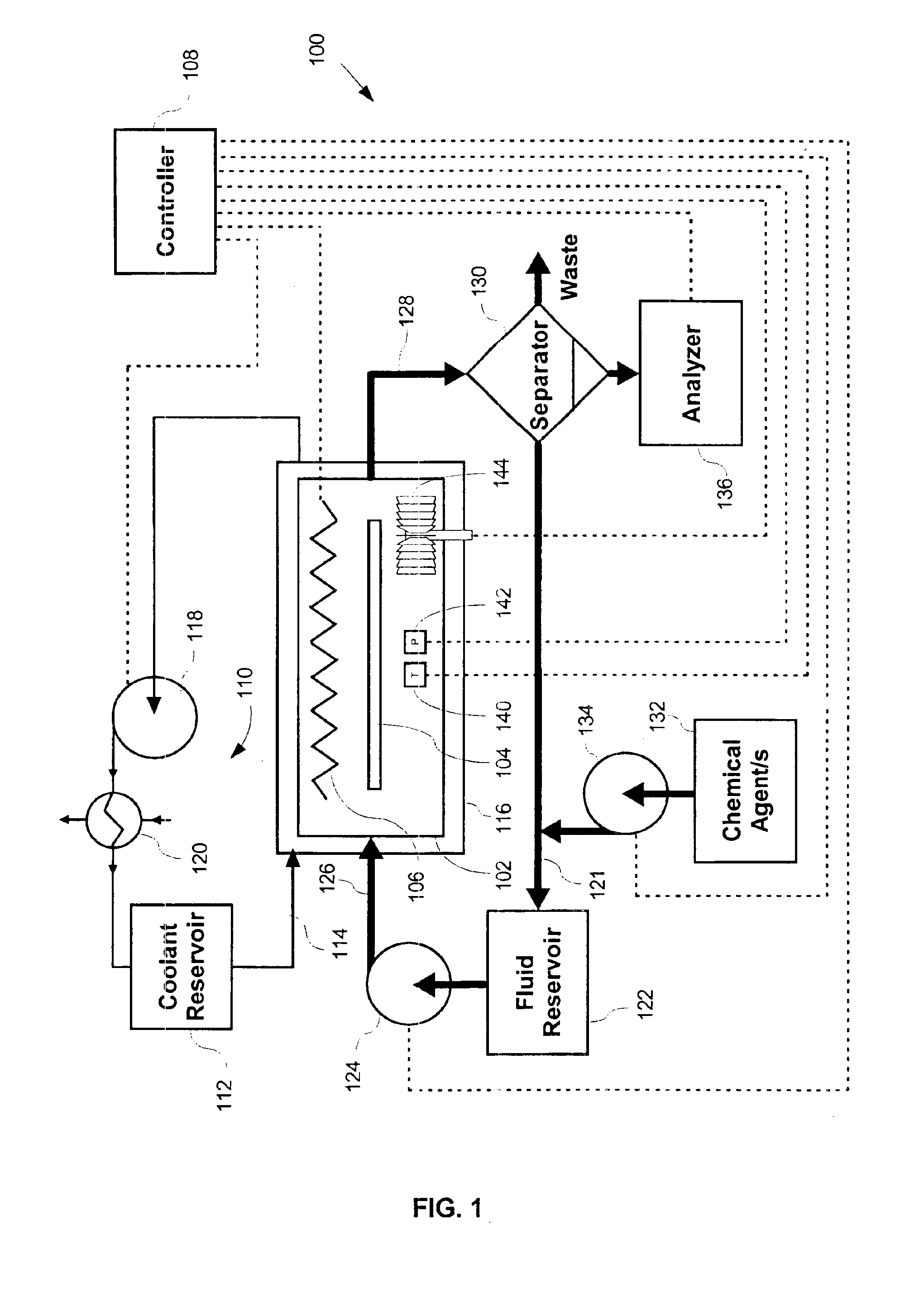
FIG. 1 is a diagrammatic block diagram of an automated dense phase fluid cleaning system 100 according to an embodiment of the invention. The system 100 is used for cleaning a substrate 104. The substrate 104 is preferably a semiconductor wafer, but may be any other component that requires cleaning. Although only one substrate is described in the following detailed description, it should be appreciated that any number of substrates may be processed concurrently. For example, the substrate 104 could consist of a batch of multiple individual substrates. Indeed, it is common for twenty-five to one hundred wafers to be processed concurrently in a semiconductor batch, where the cleaning system 100 is configured to accommodate the entire batch of substrates.

The dense phase fluid cleaning system 100 preferably includes a cleaning chamber 102 in which dense phase fluid is used to clean the substrate 104. Dense phase fluids include any of the known gases which may be converted to supercritic...


PUM


Abstract

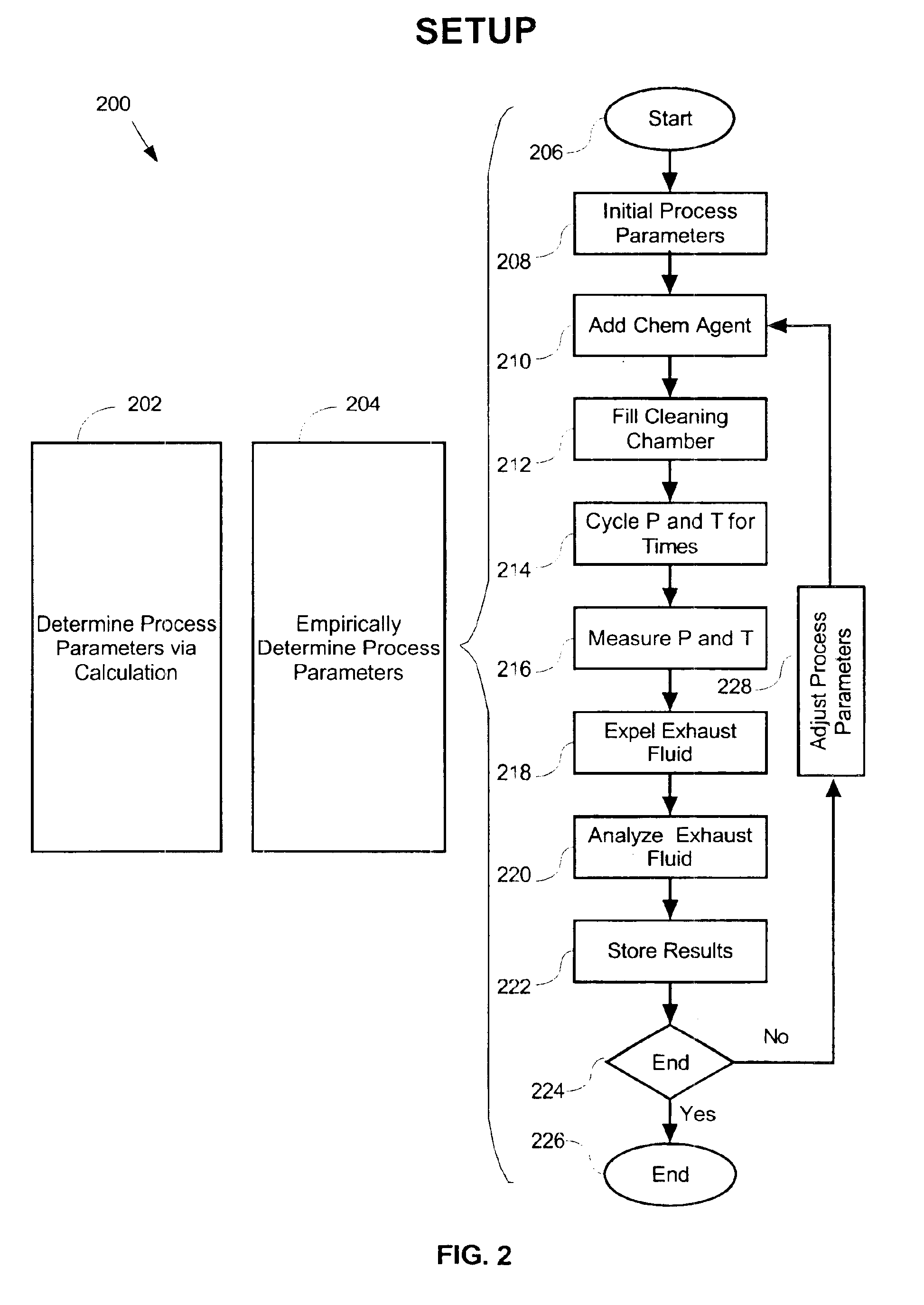
Initially, process parameters for dense phase fluid cleaning are determined. Thereafter, a cleaning chamber containing a substrate is pressurized with a dense phase fluid, based on these process parameters. The substrate is then cleaned with the dense phase fluid, again based on these process parameters. Exhaust fluid is subsequently expelled from the cleaning chamber, and thereafter analyzed. The process parameters are then adjusted to adjusted process parameters based on the analysis of the exhaust fluid. Thereafter, the cleaning chamber is again pressurized and cleaning repeated. This pressurization and cleaning is based on the adjusted process parameters. Also, this pressurization and cleaning is repeated until the substrate is sufficiently clean.

Description

BACKGROUND OF THE INVENTION1. Field of the InventionThe present invention relates generally to semiconductor substrate cleaning systems. More particularly, the present invention relates to an automated system and method for controlling a dense phase fluid cleaning system by analyzing contaminant removal.2. Description of Related ArtGenerally, semiconductor substrates, such as silicon wafers, are processed into semiconductor chips by sequentially exposing each substrate to a number of individual processes, such as photo masking, etching, implantation, and cleaning. Cleaning typically requires cleaning resist and / or etching residue from the surface of the substrate.Generally, there are two methods for cleaning the surface of a substrate, namely, wet and dry processing. Wet processing consists of a series of steps of spraying and / or immersing the substrate in expensive chemical solutions or solvents. These conventional solvent aided cleaning processes are currently being re-evaluated d...

Claims


Application Information

Patent Timeline
IPC IPC(8): B01D11/02B08B3/00B08B7/00H01L21/00
CPCB01D11/0203B08B3/00H01L21/67253B08B7/0021Y10S134/902
Inventor FURY, MICHAEL A.SHERRILL, ROBERT W.
Owner EKC TECH
Learn More