
Wind shear detection system

a detection system and wind shear technology, applied in the field can solve the problems of limited introduction of ground-based limited use of wind shear detection system,

Inactive Publication Date: 2005-02-15
SWAN INT SERVICES
View PDF13 Cites 25 Cited by
  • Summary
  • Abstract
  • Description
  • Claims
  • Application Information

AI Technical Summary

Benefits of technology

It is an object of the present invention to provide an improve airborne system for detecting atmospheric conditions.

Problems solved by technology

Windshear is a problem experienced by aircraft as a result of rapidly changing wind conditions.
Recent advances in Ground Based Weather Detection Systems have seen the limited introduction of Ground Based Windshear Detection systems.
In view of complexity and cost of such systems their use is often restricted to facilities of very high traffic usage.
While such systems provide additional information their benefit is restricted as they do not provide for the advanced prediction of dangerous windshear conditions.
Unfortunately, such equipment is unable to detect localised conditions as may impact an aircraft during the critical landing and take off phases.
Hoowever, such equipment is unable to detect wind speed changes as may impact an aircraft during the critical landing and take off phases.
Such equipment is unable to detect localised conditions as may impact an aircraft during the critical landing and take off phases.

Method used


Image

  • Wind shear detection system
  • Wind shear detection system
  • Wind shear detection system

Examples


Embodiment Construction

The preferred embodiment detects wind shear conditions by utilising a laser Doppler velocimeter. The velocimeter measures the wind speed by using the wavelength shift that is caused by the Doppler effect. Additional features are included in the preferred embodiment to identify the wind as a headwind or tailwind.

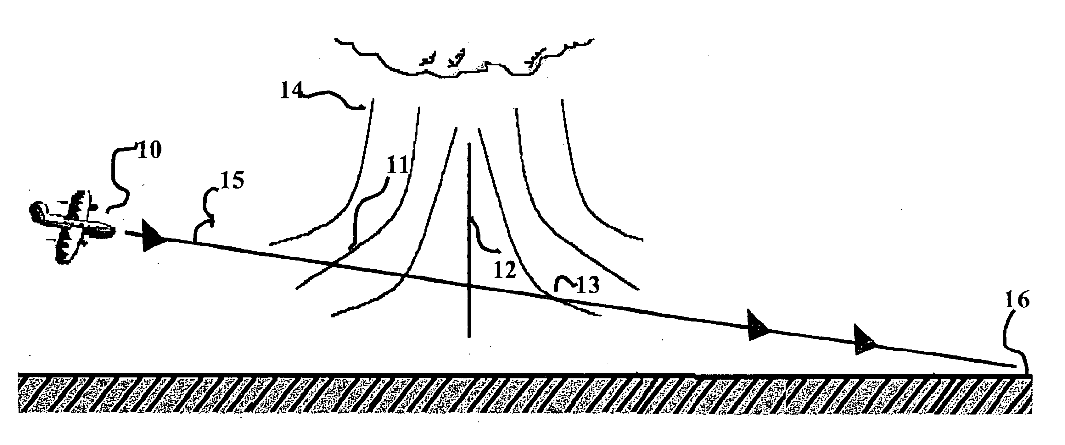
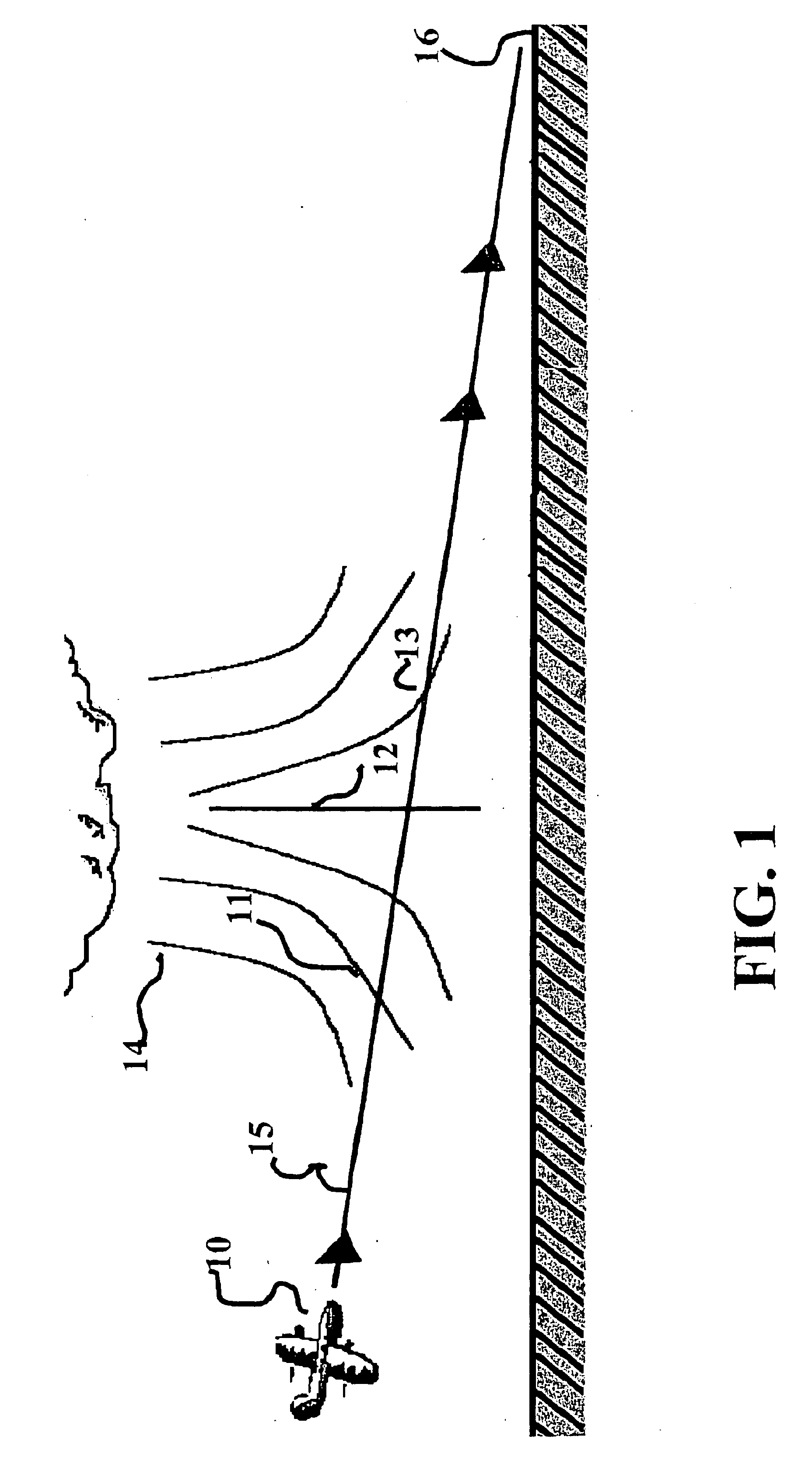
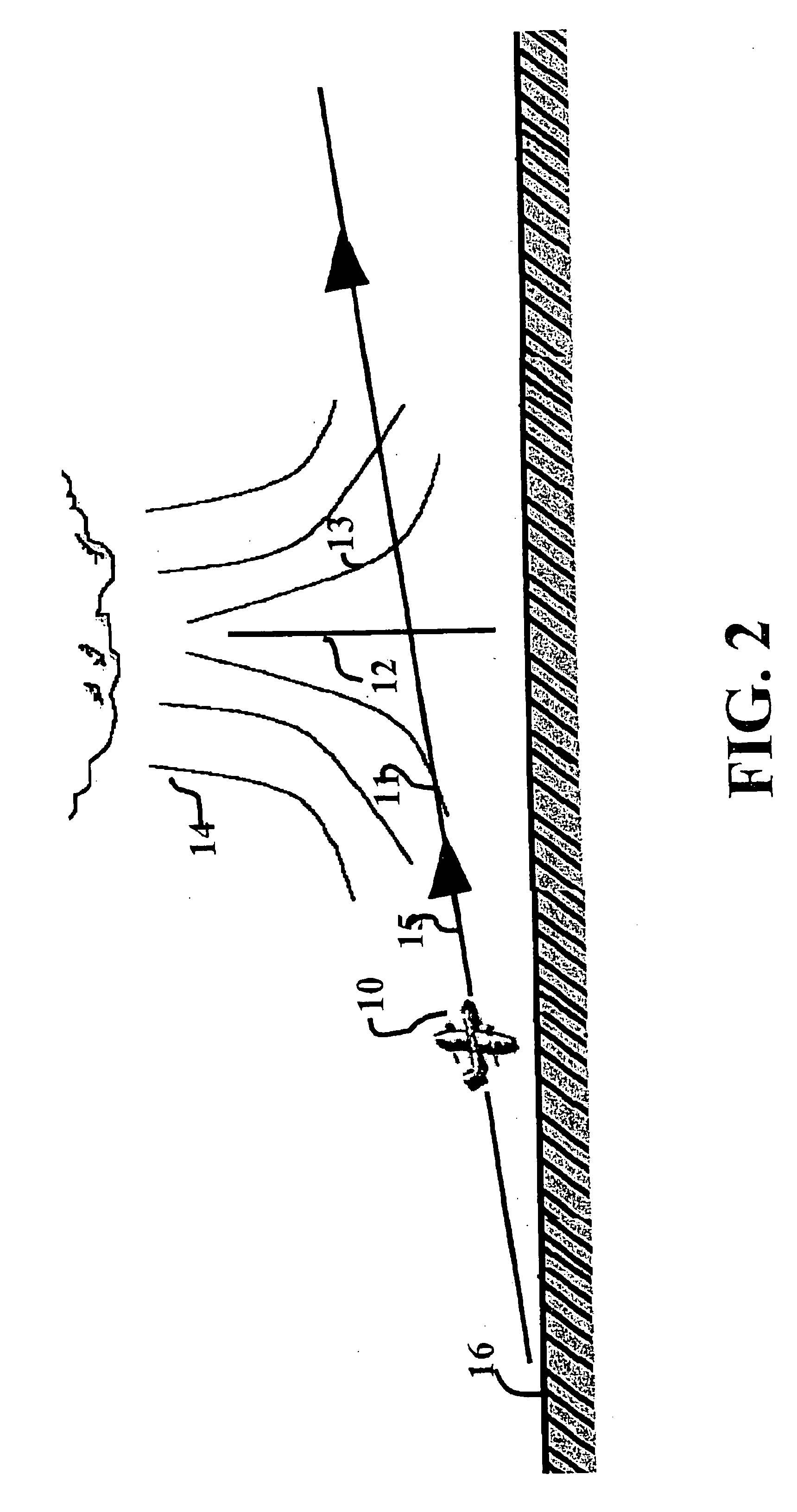
Turning initially to FIG. 1, there is provided a schematic example of the wind characteristics associated with a microburst structure 14. This structure 14 can be up to 4 kilometers in diameter. An aircraft 10 following a flight path 15 on approach to land at landing area 16 experiences the microburst 14. A substantial region of downdraft 12 exists in the centre of such a microburst structure 14. This down draft spreads horizontally closer to the ground. An aircraft 10 on a fight path 15 will initially experience a headwind 11 upon encountering the microburst. As the aircraft nears the centre of the microburst it will experience significant downdraft 12 and then a shift to a ...


PUM


Abstract

An Airborne Windshear Detection System measures wind during the Take off and Landing phase by determining the Doppler Shift of backscattered radiation that is transmitted by an on-board laser system. The collected, scattered light is mixed with a sample from the transmitting Laser using a Dual Differential Mach-Zehnder Interferometer technique. The resulting frequency shift determines the presence of dangerous windshear in the anticipated trajectory of the aircraft.

Description

FIELD OF THE INVENTIONThe present invention relates to aircraft on-board detection and predicting of atmospheric conditions including dangerous windshear conditions which may dangerously occur during the critical landing and take off phase.BACKGROUND OF THE INVENTIONWindshear is a problem experienced by aircraft as a result of rapidly changing wind conditions. On approach to landing a performance-increasing headwind may be replaced by a performance-decreasing tailwind. An airborne forward looking windshear detector can warn a pilot that he is approaching a windshear hazard.Recent advances in Ground Based Weather Detection Systems have seen the limited introduction of Ground Based Windshear Detection systems. An example of which is disclosed in U.S. Pat. No. 6,272,433. In view of complexity and cost of such systems their use is often restricted to facilities of very high traffic usage.Recent advances in Airborne Equipment such as that disclosed in U.S. Pat. No. 6,188,330 act to detec...

Claims


Application Information

Patent Timeline
Patent Type & Authority Patents(United States)
IPC IPC(8): G01S17/95G01S17/58G01S17/00G01S7/48G01S7/483
CPCG01S7/483G01S17/95G01S17/58Y02A90/10
Inventor MCGUIRE, BRIAN
Owner SWAN INT SERVICES
Learn More