Method and apparatus for pest deterrence

a technology of pest deterrent and electronic device, applied in the direction of alarms, signalling systems, instruments, etc., can solve the problem of creating even more disturbing ultrasound, and achieve the effect of reducing sound levels, preserving power, and convenient verification of sonic outpu

Inactive Publication Date: 2005-02-15
TIM SIMON
View PDF19 Cites 17 Cited by
  • Summary
  • Abstract
  • Description
  • Claims
  • Application Information

AI Technical Summary

Benefits of technology

An efficient pest deterrent device uses a detector that provides a detection signal to a microprocessor. The microprocessor is used to directly generate ultrasound, as well as control the operation and timing of the device. For example, the microprocessor can detect if the device is operated on line or battery power, and change device operation to conserve power when the device is battery-operated. The device can thus operate in a variety of modes. On line power, the device alternates between two ultrasonic tones until a pest is detected, at which point the devices changes the ultrasonic output to a sweeping output. The ultrasonic sweep can be combined with a flash, preferably delayed from the onset of the swept signal by about one second. This delay allows the attention of the pest to be drawn to the ultrasound, and the flash to startle or otherwise drive off the pest. In a further embodiment, the strobe charging circuit's oscillator signal can be used to amplitude modulate (“AM”) the ultrasound to create noisy sidebands from high ultrasonic down to within the normal range of human hearing. This AM creates even more disturbing ultrasound and also allows an operator to conveniently verify sonic output but at much lower sound levels than the ultrasound.

Problems solved by technology

This AM creates even more disturbing ultrasound and also allows an operator to conveniently verify sonic output but at much lower sound levels than the ultrasound.

Method used


Image

  • Method and apparatus for pest deterrence
  • Method and apparatus for pest deterrence
  • Method and apparatus for pest deterrence

Examples


Embodiment Construction

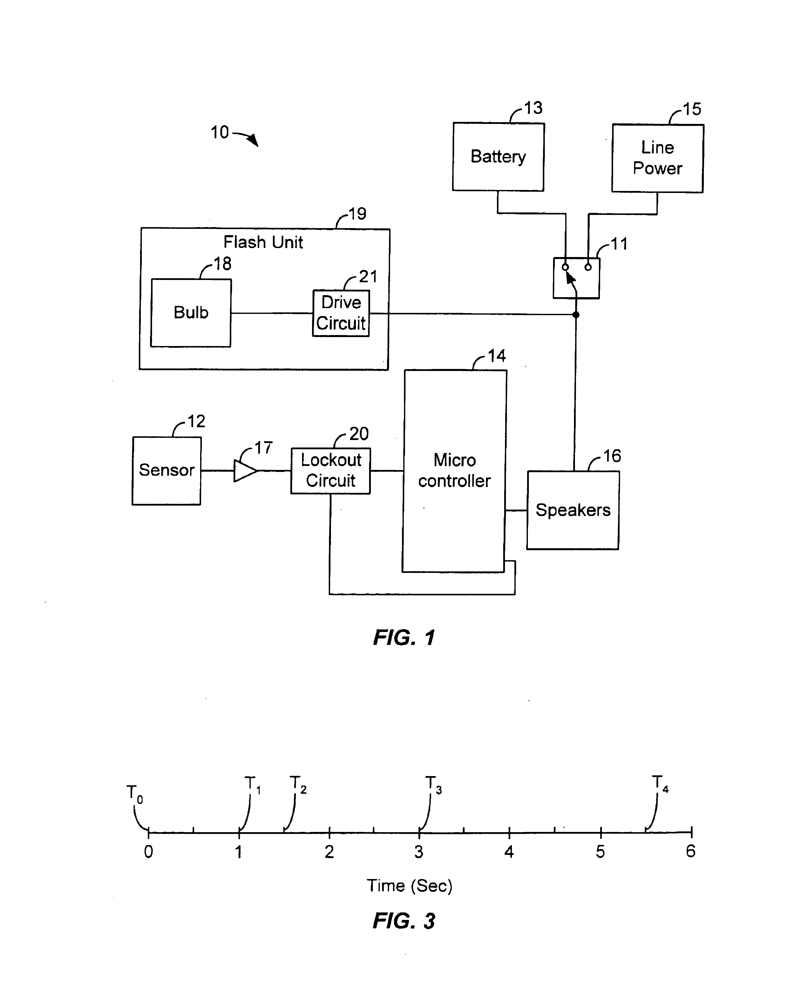
The present invention provides an ultrasonic pest deterrent. Various operating conditions can be selected depending on the type of power source available (e.g. line power or battery operation), and the ultrasonic deterrent signal can be combined with a flashing light for enhanced deterrent effect. In one embodiment, the ultrasonic signal is initiated when a pest, such as a deer or dog, is detected. A selected period of time lapses before the flash is discharged, thus ultrasound draws the attention of the pest in the direction of the device, and the flash startles the pest. In a particular embodiment, the ultrasonic sound is generated with a microprocessor and the low-frequency flash oscillator AM modulates the ultrasound signal to produce sidebands of ultrasonic signal down to some frequencies within the range of normal human hearing but at much lower levels. This allows an operator to verify that the device is activated and the speakers are on.

I. An Exemplary Pest Deterrent Device

F...


PUM


Abstract

A pest deterrent device attracts the attention of a pest with ultrasonic noise and then produces a series of flashes to drive off the pest. In one embodiment, the device continuously produces ultrasound, changing the ultrasound when a pest is detected. In another embodiment, the device does not produce ultrasound until a pest is detected. In a further embodiment, the flash charging circuit is used to modulate the ultrasound while the flash is operated. In a particular embodiment, four ultrasonic speakers are arranged in a series-parallel configuration with a total capacitance of about 0.2 micro-Farads achieve 120 dB of sound output with a supply voltage of about 12-18 V.

Description

STATEMENT AS TO THE RIGHTS TO INVENTION MADE UNDER FEDERALLY SPONSORED RESEARCH AND DEVELOPMENTNot applicable.BACKGROUND OF THE INVENTIONThe present invention relates generally to electronic pest deterrent devices and more particularly to pest deterrent devices that emit ultrasound to drive off animals.Pests, such as birds, deer, cats, dogs, or rodents among others, can cause significant damage to crops, buildings, stored goods, and landscaping. A variety of methods and devices have been employed to attempt and reduce the damage caused by pests. Some approaches use a scarecrow or replica of a predator, such as an owl or snake, to scare away pests. Unfortunately, pests often become accustom to these devices and they lose their effectiveness.Other approaches use noise, such as a series of small explosive devices linked to a slow-burning fuse, and / or propane guns to scare away pests. Such methods might be inappropriate in an area where the noise would be bothersome. Additionally, the p...

Claims


Application Information

Patent Timeline
Patent Type & Authority Patents(United States)
IPC IPC(8): A01M31/00A01M29/00A01M29/02A01M29/10A01M29/18
CPCA01M29/10A01M31/002A01M29/18
Inventor SMITH, BLAINE M.SIMON, TIMOTHY M.
Owner TIM SIMON
Why Eureka
Try Eureka