
Kennel floor system

Inactive Publication Date: 2005-02-15
BAUMAN RAYMOND J
View PDF20 Cites 7 Cited by
  • Summary
  • Abstract
  • Description
  • Claims
  • Application Information

AI Technical Summary

Benefits of technology

The primary object of the present invention is to provide an improved kennel floor system that can be efficiently assembled and disassembled.
An important object of the present invention is to provide a durable kennel floor system.
An important object of the present invention is to provide a kennel floor system that is easy to clean.
An important object of the present invention is to provide a kennel floor system that includes proper accommodations for animals.

Problems solved by technology

However, it has been found that some of these prior systems cannot be efficiently assembled and disassembled.
Further, some of these systems are weak, difficult to clean and fire hazards.
Finally, it has been found that some of these prior systems do not provide satisfactory accommodations for animals.

Method used


Image

  • Kennel floor system
  • Kennel floor system
  • Kennel floor system

Examples


Embodiment Construction

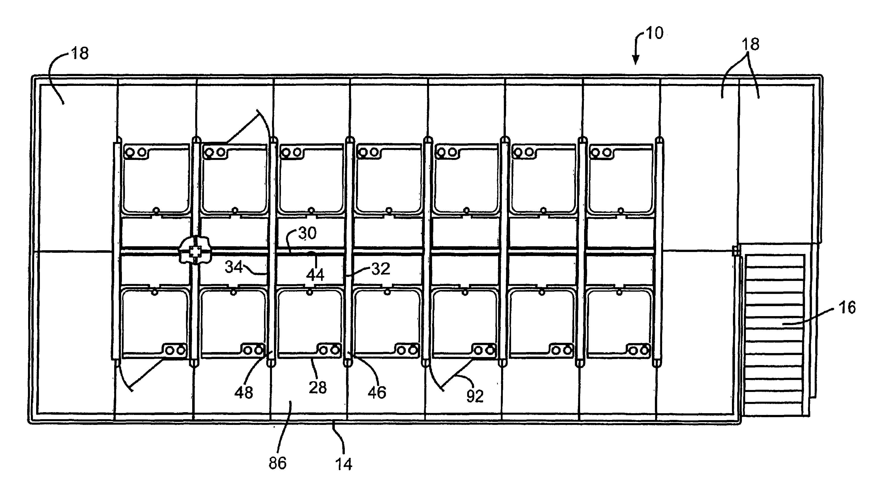
The preferred embodiments and best mode of the present invention will now be described in detail with reference being made to the drawings. The kennel floor system of the present invention is indicated generally in the drawings by the reference number “10”.

Referring to FIGS. 1-3, the kennel floor system 10 includes a plurality of lower floor units 12 and a plurality of upper floor units 14. In the present embodiment, there are nineteen lower floor units 12 and fourteen upper floor units 14. However, it should be understood that the number of lower and upper floor units 12 and 14 can vary depending upon the number of units desired and the size and shape of a building in which the system 10 is constructed. The building can be an existing structure or it can be a new construction designed specifically for use with the system 10. The system 10 can be disassembled for movement and reassembly in another building.

Referring still to FIGS. 1-3, the system 10 is two-story and includes a stair...


PUM


Abstract

A kennel floor system for use in a building including a lower floor unit and an upper floor unit supported on walls that extend between the lower and upper floor units.

Description

BACKGROUND OF THE INVENTIONThe present invention relates to animal housing. More specifically, the invention is directed to a kennel floor system.In the past, kennels were constructed of cages on the floor of a building. In most cases, the floors were flat and did not include drainage.Modular kennel structures were developed that included various types of flooring, cages and drainage systems. However, it has been found that some of these prior systems cannot be efficiently assembled and disassembled. Further, some of these systems are weak, difficult to clean and fire hazards. Finally, it has been found that some of these prior systems do not provide satisfactory accommodations for animals.There is a need for a durable, easy to clean, fire proof kennel floor system that can be efficiently assembled and disassembled. Further, there is a need for a kennel floor system that provides proper accommodations for animals in the system. The present invention satisfies these and other needs.S...

Claims


Application Information

Patent Timeline
IPC IPC(8): A01K1/015A01K1/03A01K1/02
CPCA01K1/034A01K1/015
Inventor BAUMAN, RAYMOND J.
Owner BAUMAN RAYMOND J
Learn More