
Apparatus for cleaning optical fiber connectors and fiber optic parts

a technology for fiber optic connectors and cleaning apparatus, which is applied in the direction of cleaning process, cleaning apparatus, and liquid cleaning, etc., can solve the problems of degrading affecting the performance of optical fiber telecommunications equipment, and residual cleaner materials such as cotton fibers on the connectors, etc., and achieves the effect of cleaning various

Inactive Publication Date: 2005-02-08
LIGHTEL TECH
View PDF10 Cites 61 Cited by
  • Summary
  • Abstract
  • Description
  • Claims
  • Application Information

AI Technical Summary

Benefits of technology

Advantageously, the apparatus according to embodiments of the present invention are capable of cleaning various types of male or female optical fiber connectors as well as other optical fiber parts thoroughly and efficiently.

Problems solved by technology

During the use of optical fiber communications equipment, various contaminants including dust, finger oils, and grease may accumulate in optical fiber connectors and settle on fiber and ferrule end surfaces.
The presence of such contaminants may significantly attenuate or even completely block the transmission of optical signals through the optical fiber connectors, or cause undesirable reflection of optical signals, thereby significantly degrading the performance of the optical fiber telecommunications equipment.
A disadvantage associated with the above methods is that some residual cleaner materials such as cotton fibers may remain on the connectors.
Furthermore, they cannot be conveniently used for female connector cleaning.
This conversion is typically very inconvenient and time consuming.
However, this method is usually ineffective and costly.

Method used


Image

  • Apparatus for cleaning optical fiber connectors and fiber optic parts
  • Apparatus for cleaning optical fiber connectors and fiber optic parts
  • Apparatus for cleaning optical fiber connectors and fiber optic parts

Examples


Embodiment Construction

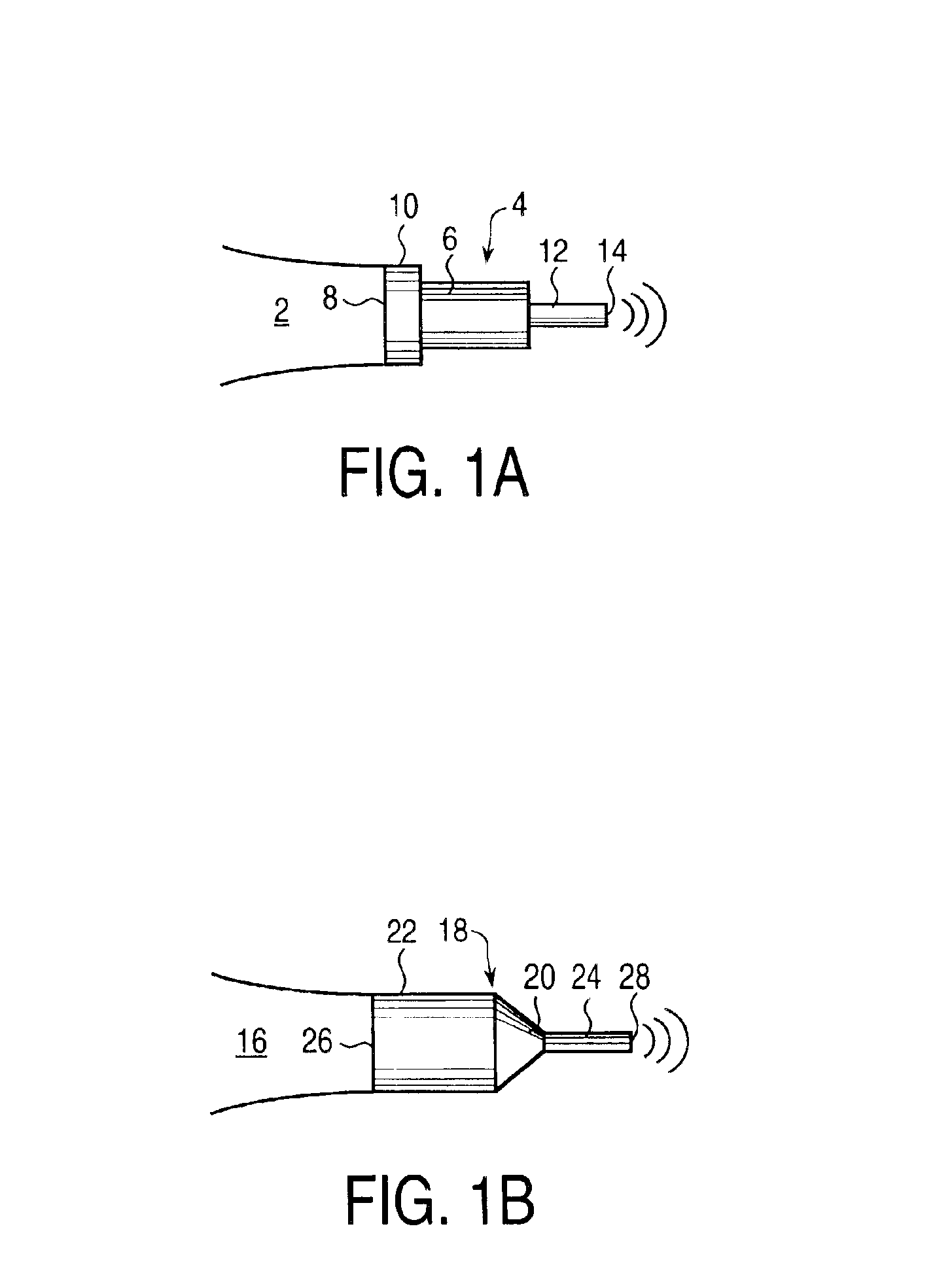
FIG. 1A is a side view of an ultrasound transducer 2 and a resonant ultrasound launcher with three stages of stepped portions 10, 6, and 12. In this embodiment, the ultrasound transducer 2 has a transducer end 8 that is connected to the base portion 10 of the resonant ultrasound launcher 4. The ultrasound transducer may be a conventional piezo-electric transducer that produces mechanical vibrations at ultrasonic frequencies in response to electrical pulses applied to the transducer. Because conventional piezo-electric ultrasound transducers are well known to a person skilled in the art, only the end portion of the ultrasonic transducer 2 is shown in FIG. 1A to simplify the illustration.

In an embodiment, the resonant ultrasound launcher 4 is made of the same metallic material as that of the ultrasound transducer 2, to prevent reflection of sound waves at the transducer end 8 that is connected to the base portion 10 of the resonant ultrasound launcher 4. Moreover, the base portion of ...


PUM


Abstract

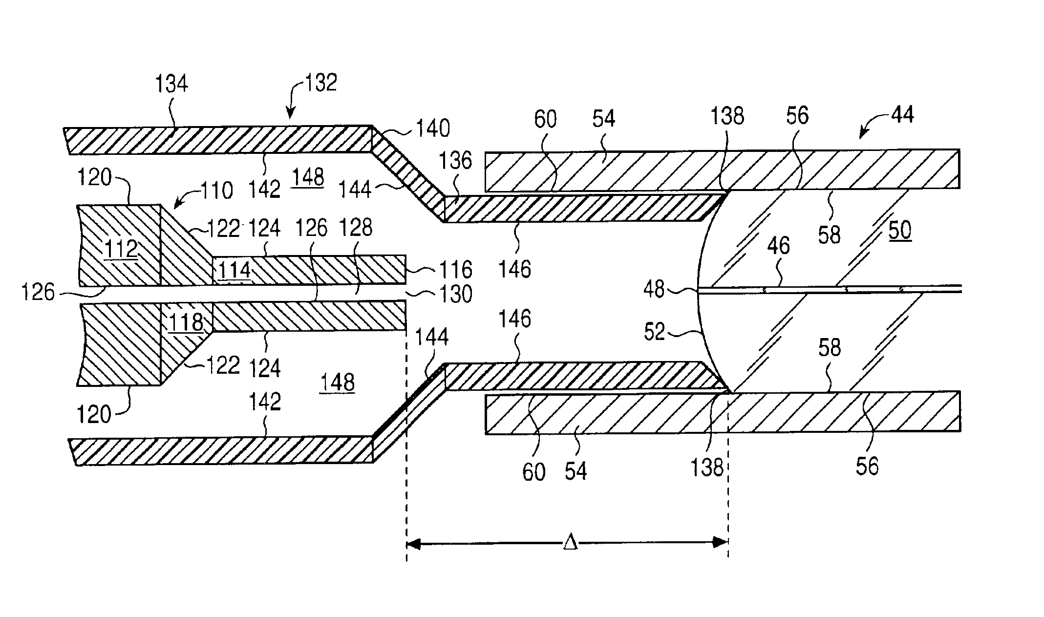
An apparatus comprising an acoustically resonant ultrasound launcher is provided for cleaning of optical fiber connectors and other optical fiber parts. The resonant ultrasound launcher is designed to transfer and to focus ultrasonic energy from an ultrasound transducer to a relatively small target area with high intensity. Specially designed fluid flow channels allow this apparatus to efficiently clean optical fiber connectors with an exposed end surface or with an end surface concealed in a connector adapter. Circuitry is provided to automatically track the frequency to enhance the ultrasound generation. Another circuitry is provided to program the sequence of the cleaning process, including washing, rinsing and drying.

Description

BACKGROUND OF THE INVENTION1. Field of the InventionThe present invention relates to the cleaning of optical fiber connectors, particularly to the cleaning of in-adapter optical fiber connectors, and more particularly, to ultrasound apparatus for cleaning optical fiber connectors.2. Background ArtIn a typical optical fiber connector, an optical fiber has a terminal portion which has a side wall surrounded by a ferrule. An adapter is needed to couple the light from the fiber in one connector to the fiber in another connector. A pair of connector ferrules can be accurately aligned face to face via the sleeve inside the adapter. An in-adapter connector, i.e., an assembly with a connector that is plugged into an adapter, is typically referred to as a “female” connector, whereas a free connector which is not in an adapter is typically referred to as a “male” connector. Female connectors can exist in many fiber optic systems and equipment, e.g. on connector rack panels or instrument front...

Claims


Application Information

Patent Timeline
Patent Type & Authority Patents(United States)
IPC IPC(8): B08B3/12G02B6/38
CPCB08B3/12G02B6/3866G02B6/3807B08B2240/02
Inventor LU, LEHUANG, SHANGYUANMAO, ZHONGMINGSUN, KE-XUN
Owner LIGHTEL TECH
Learn More