
Fluid separation and delivery apparatus and method

Inactive Publication Date: 2005-02-08
PATENT INNOVATIONS +1
View PDF22 Cites 197 Cited by
  • Summary
  • Abstract
  • Description
  • Claims
  • Application Information

AI Technical Summary

Benefits of technology

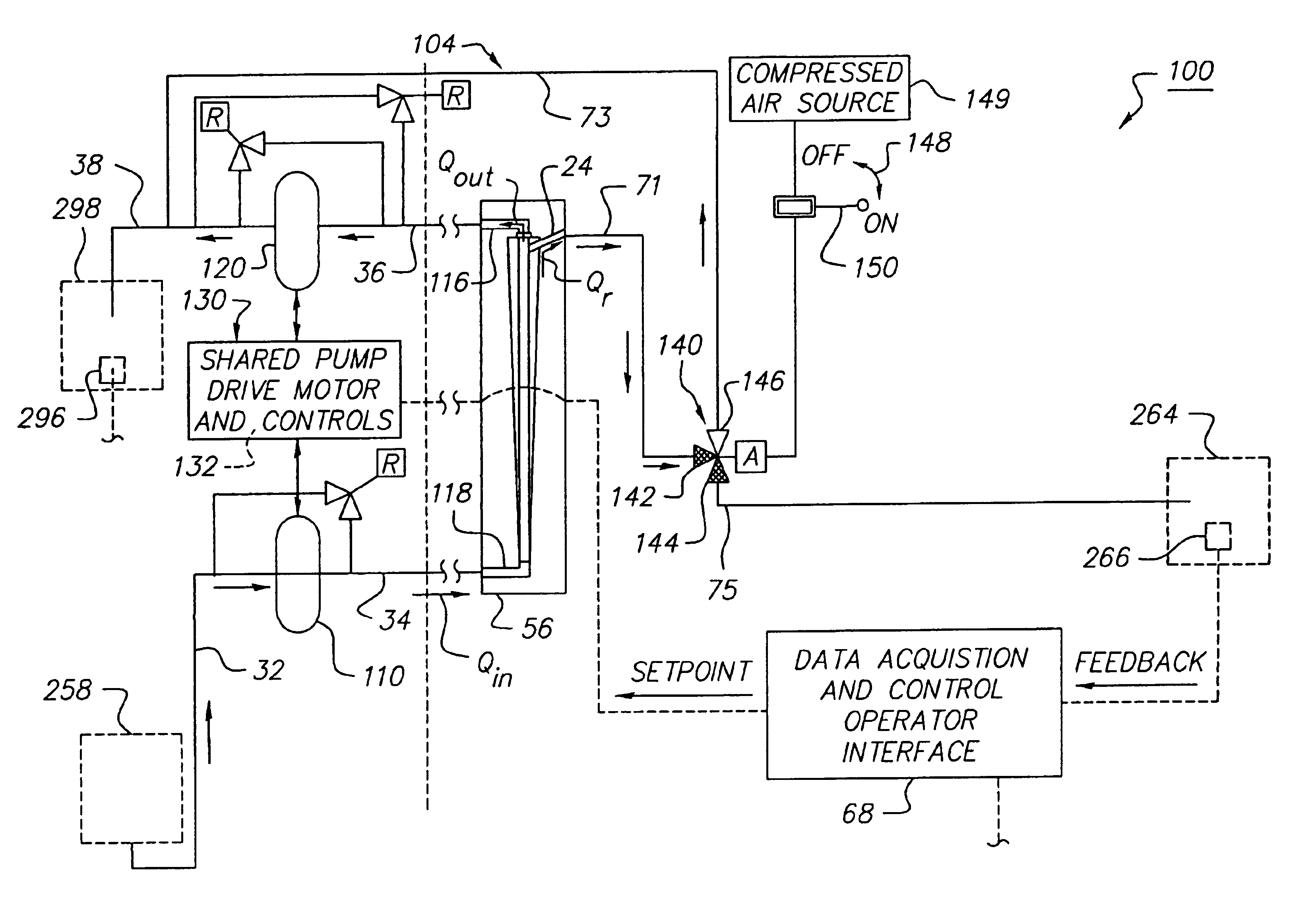
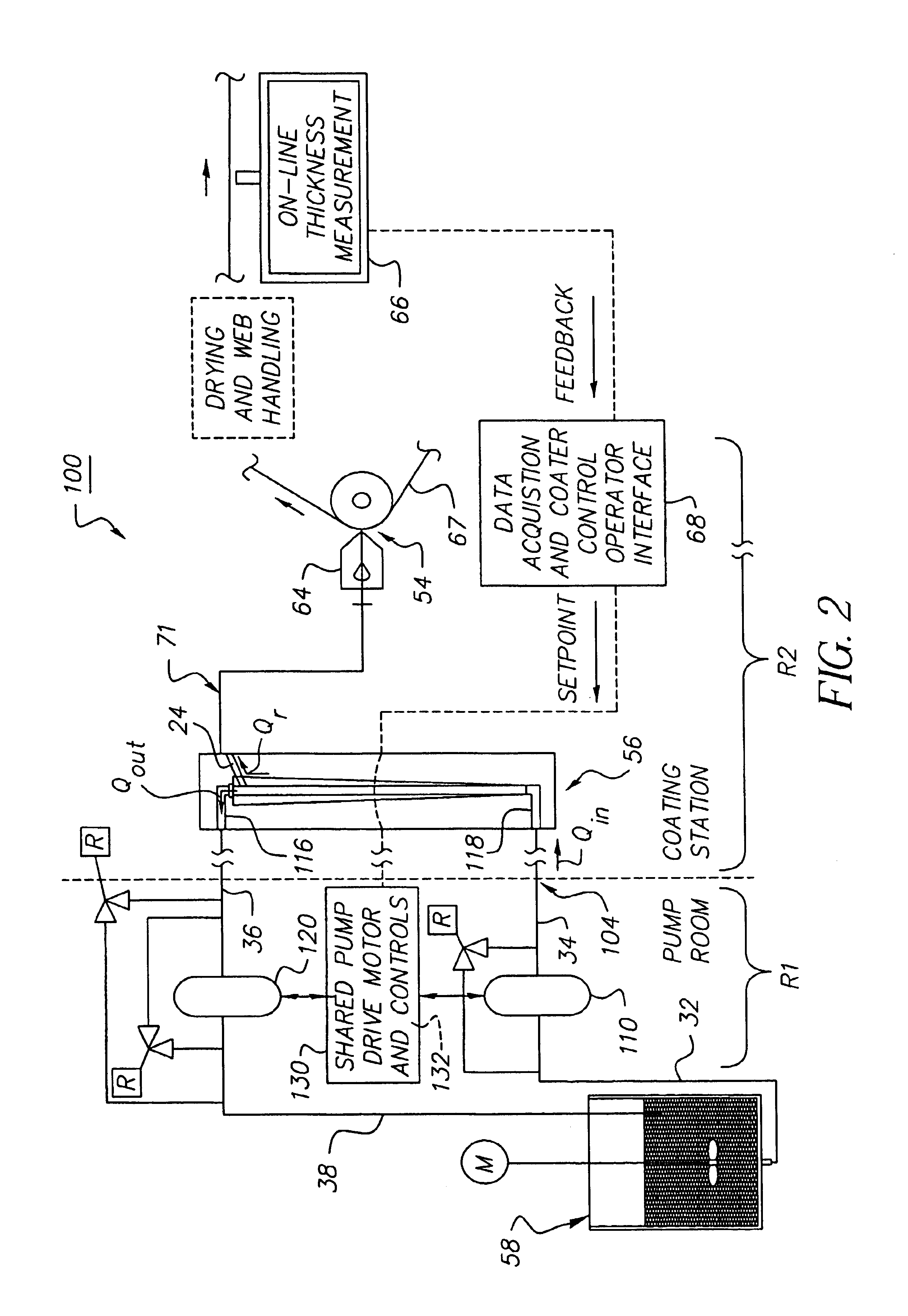
In accordance with the present invention, there is provided a fluid separation and delivery apparatus for filtering a fluid from a source and delivering a filtrate derived from said fluid from said source to a first destination, and delivering a decantate derived said fluid from said source to a second destination comprising a filter device having an inlet port for connecting to a fluid source, a first outlet port for directing said filtrate to said first destination, and a second outlet port for directing said decantate to said second destination; an inlet pump connected between said inlet port of said filter device and said fluid source for pumping fluid at a flow rate of Qin into said filter device; and an outlet pump connected between said second outlet port of said filter device and said second destination for pumping said decantate at a flow rate of Qout out of said filter device to said second destination, wherein said outlet pump and said inlet pump are sized and controlled so that Qout is less than Qin, and so t

Problems solved by technology

The pigment and binder resin are chosen to optimize their photoconductive properties, but it is not always possible to optimize the dispersion quality of the resulting coating fluid.
Charge generating dispersions that become unstable over time are a common problem in the fabrication of certain organic photoreceptors.
Unstable dispersions and particulate impurities result in coating defects in the charge generating layer that lower coating yield during the fabrication process.
The flow field moves the flocs onto the surface and into the bulk of the filter medium, ultimately resulting in plugging of the filter.
In photoreceptor manufacturing or similar film or web coating operations, a plugged filter may cause a significant amount of downtime for a filter change, including restart and stabilization of the coating process (for example, for the purging of air bubbles from the filter device).
This is obviously a costly interruption of such manufacturing process.
Attempts to filter the dispersion using filter elements rated to retain particles small than 40 microns resulted in plugging of the filters with pigment flocs.
However, in embodiments of organic photoreceptor manufacturing, and other thin film device manufacturing, it is undesirable to use a filter that will allow the passage of particles in the 1 micron to 40 micron size range.
Such particles and / or flocs may disrupt flow out of the extrusion die or other coating applicator, causing streaks.
Also, the presence of particles of this large a size in the wet coated generator layer is known to result in defects in the dried generator layer.
Both particles and streaks will show as defects in the final printed output to the end customer; therefore, any photoreceptor having such defects will not be acceptable.
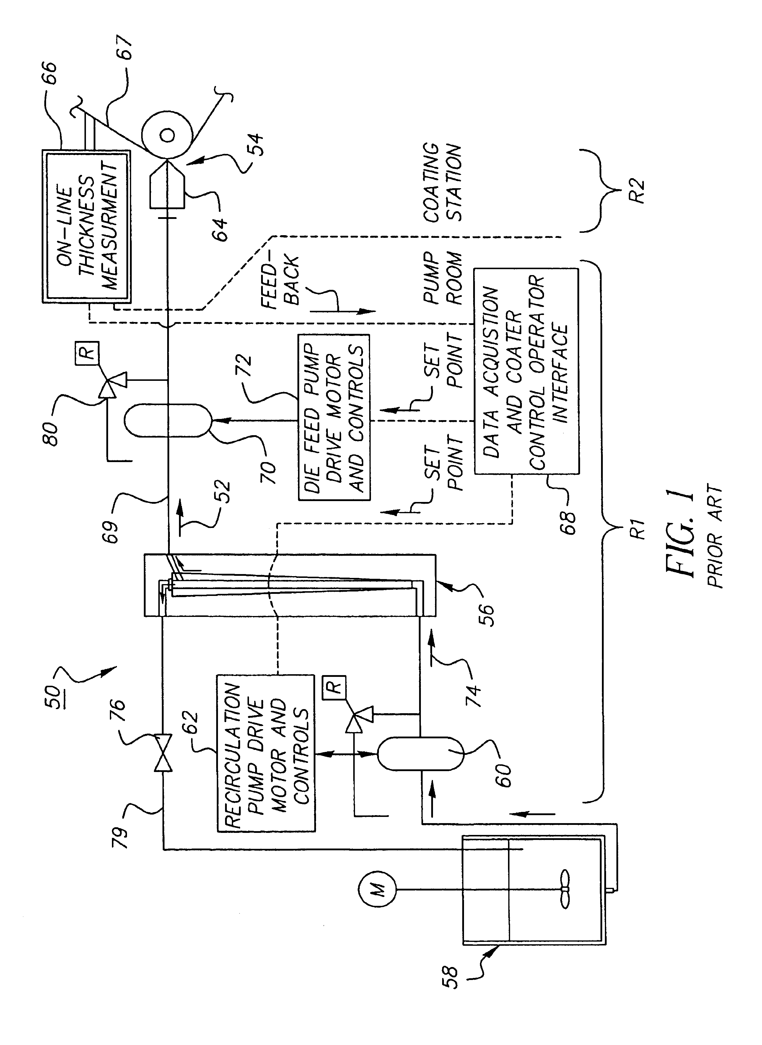
However, conventional coating fluid delivery systems in which such a filter is installed are ordinarily not optimum.
They are often complex and do not locate the filter in close proximity to the coating die or other coating applicator.
Therefore, such a conventional delivery system does not minimize the incidence of particulate defects and pigment flocs, which may be present in the coating fluid that is delivered into the die, and subsequently onto the coated film or photoreceptor.
As such, the problem of filtering the coating dispersion at a process location immediately before and in close proximity to the coating application has not been addressed.
Such a location of the filter significantly reduces the opportunity for the filtrate to be re-contaminated with undesired particles as it flows from the filter to the coating applicator.

Method used


Image

  • Fluid separation and delivery apparatus and method
  • Fluid separation and delivery apparatus and method
  • Fluid separation and delivery apparatus and method

Examples


Embodiment Construction

For a general understanding of the present invention, reference is made to the drawings. In the drawings, like reference numerals have been used throughout to designate identical elements. While the present invention will be described in connection with preferred embodiments thereof, it will be understood that it is not intended to limit the invention to such embodiments. On the contrary, it is intended to cover all alternatives, modifications, and equivalents as may be included within the spirit and scope of the invention as defined by the appended claims.

In describing the present invention, a variety of terms are used in the description. Standard terminology is widely used in filtration, fluid delivery, and general fluid processing art. As used herein, a two phase fluid is meant to be a fluid comprising a liquid phase in which either substantially solid particles are dispersed therethrough, or a first liquid phase in which droplets or particles of a second liquid phase immiscible ...


PUM

PropertyMeasurementUnit
Flow rateaaaaaaaaaa

Abstract

A fluid separation and delivery apparatus and method are provided for filtering a fluid from a source and delivering a filtrate derived therefrom to a first destination, and delivering a decantate derived therefrom to a second destination. The fluid separation and delivery apparatus for the method comprises a filter device having an inlet port for connecting to a fluid source, a first outlet port for directing filtrate to a first destination, and a second outlet port for directing decantate to a second destination; an inlet pump connected between the inlet port of the filter device and the fluid source for pumping fluid at a flow rate of Qin into the filter device; and an outlet pump connected between the second outlet port of the filter device and the second destination for pumping fluid at a flow rate of Qout out of the filter device to the second destination. The outlet pump and the inlet pump are sized and controlled so that Qout is less than Qin, and so that the resulting flow rate of filtrate Qr from the filter device through the first outlet port to the first destination is equal to Qin−Qout.

Description

This invention relates in one embodiment to a fluid processing apparatus, and more particularly to an apparatus that can separate or concentrate a first phase relative to a second phase in a flowing fluid.FIELD OF THE INVENTIONA fluid separation and delivery apparatus for separating and / or concentrating a first phase relative to a second phase in a flowing fluid, by the use of a filtration device.BACKGROUND OF THE INVENTIONThere is a need in many industries for a simple apparatus and process to separate or concentrate a first phase relative to a second phase in a two phase flowing fluid. Such commercial and industrial applications for the present invention occur in the fields of medicine, food manufacturing, energy, electronics, imaging devices, chemicals, ceramics, and many others.In one embodiment, for example, this invention relates to a liquid dispersion filtration and delivery processes in the manufacturing or fabrication of products in which effective filtration is required in...

Claims


Application Information

Patent Timeline
IPC IPC(8): B01D61/10B01D61/12B01D61/22B01D61/20B01D61/02B01D61/14B01D63/06
CPCB01D61/02B01D61/025B01D61/10B01D61/12B01D63/06B01D61/147B01D61/20B01D61/22B01D61/14
Inventor HAMMOND, JOHN M.
Owner PATENT INNOVATIONS
Learn More