
Apparatuses, methods, and computer programs for displaying information on vehicles

a technology for displaying information and vehicles, applied in the field of system for displaying information, can solve problems such as the appearance of outdated traditional signs, and achieve the effect of flexible, effective, and/or profitable use of signs

Inactive Publication Date: 2005-02-01
VERT INC
View PDF14 Cites 389 Cited by
  • Summary
  • Abstract
  • Description
  • Claims
  • Application Information

AI Technical Summary

Benefits of technology

It is an object of the present invention to provide for more flexible, effective, and / or profitable usage of signs.
Some embodiments of this aspect of the invention further include providing an on-line site from which remote computers can purchasing over a computer network the right to have messages shown on displays, including enabling on-line purchasers to separately select whether to purchase the right to have a message displayed on one or more displays as a function of their position relative to the vehicle which carries them. Such methods include controlling what messages are shown on which of the vehicle's displays as a function of the purchases made on the on-line site.

Problems solved by technology

But advances in technology have made traditional signs seem somewhat out of date.

Method used


Image

  • Apparatuses, methods, and computer programs for displaying information on vehicles
  • Apparatuses, methods, and computer programs for displaying information on vehicles
  • Apparatuses, methods, and computer programs for displaying information on vehicles

Examples


Embodiment Construction

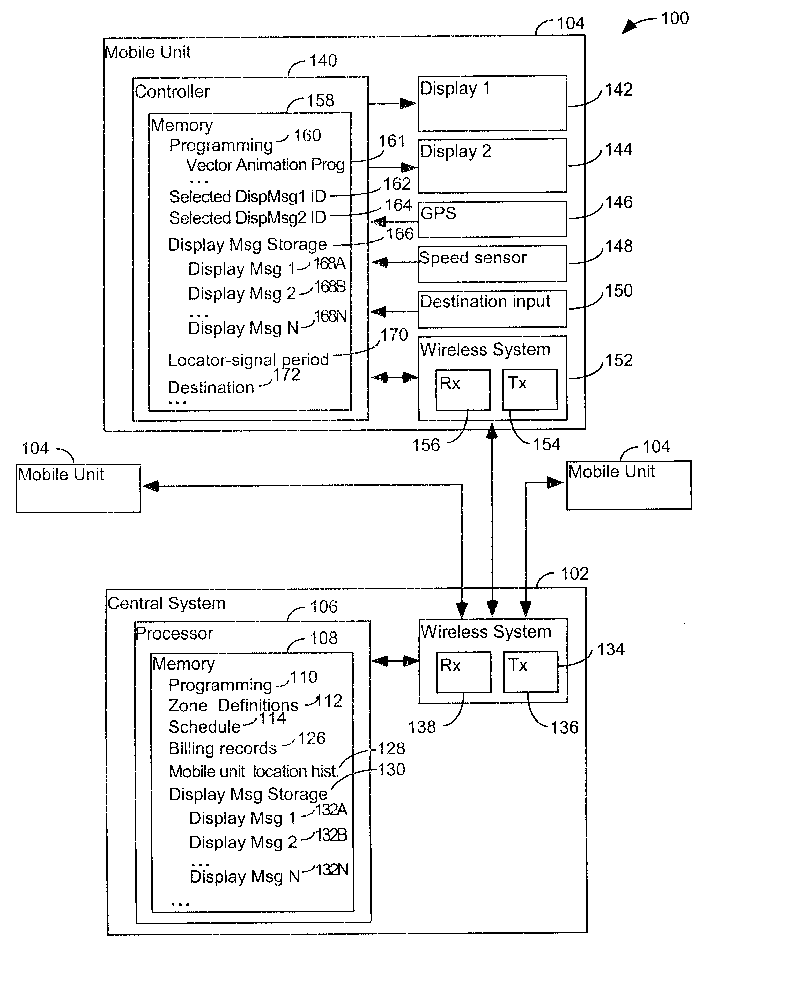
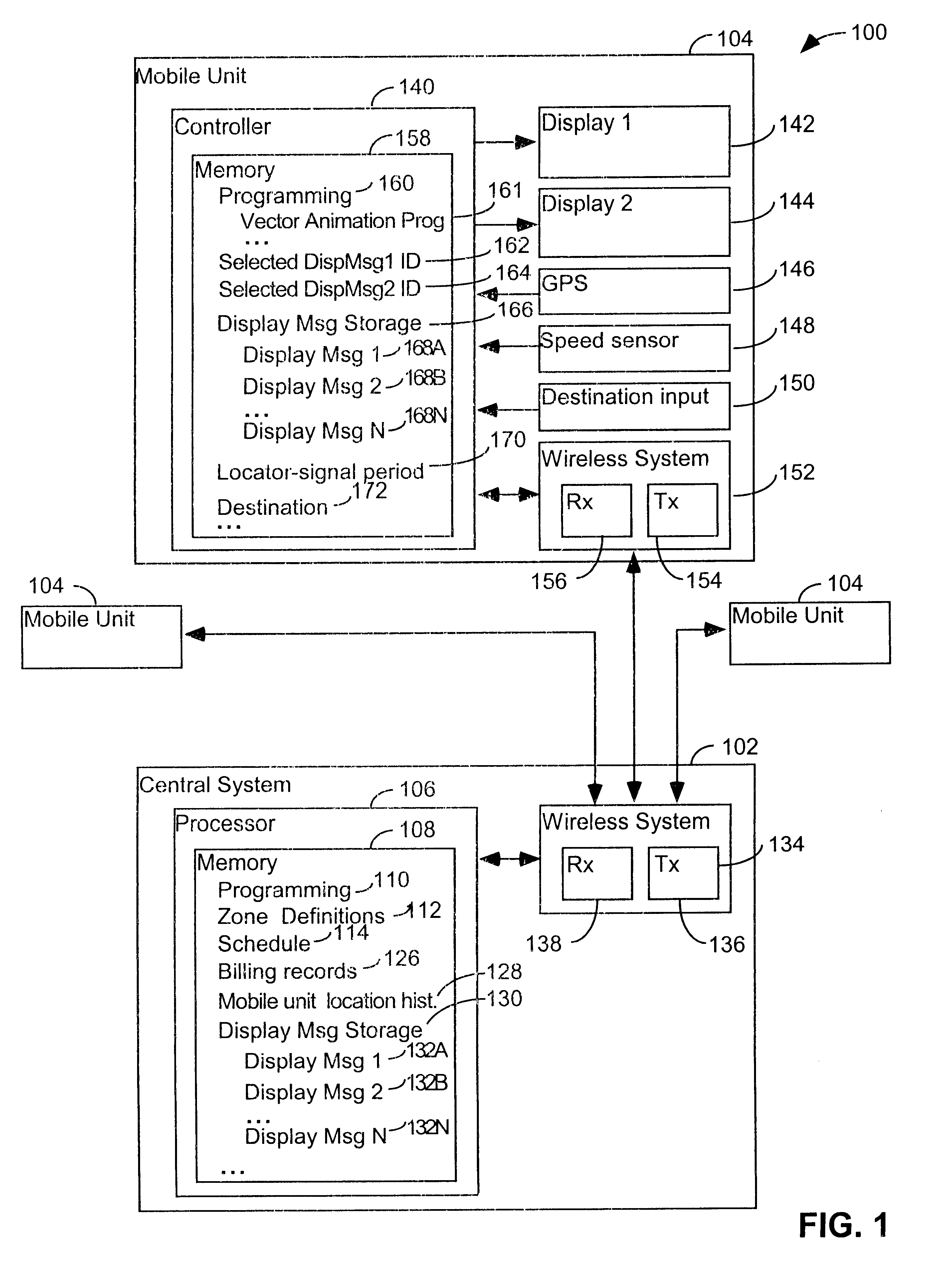
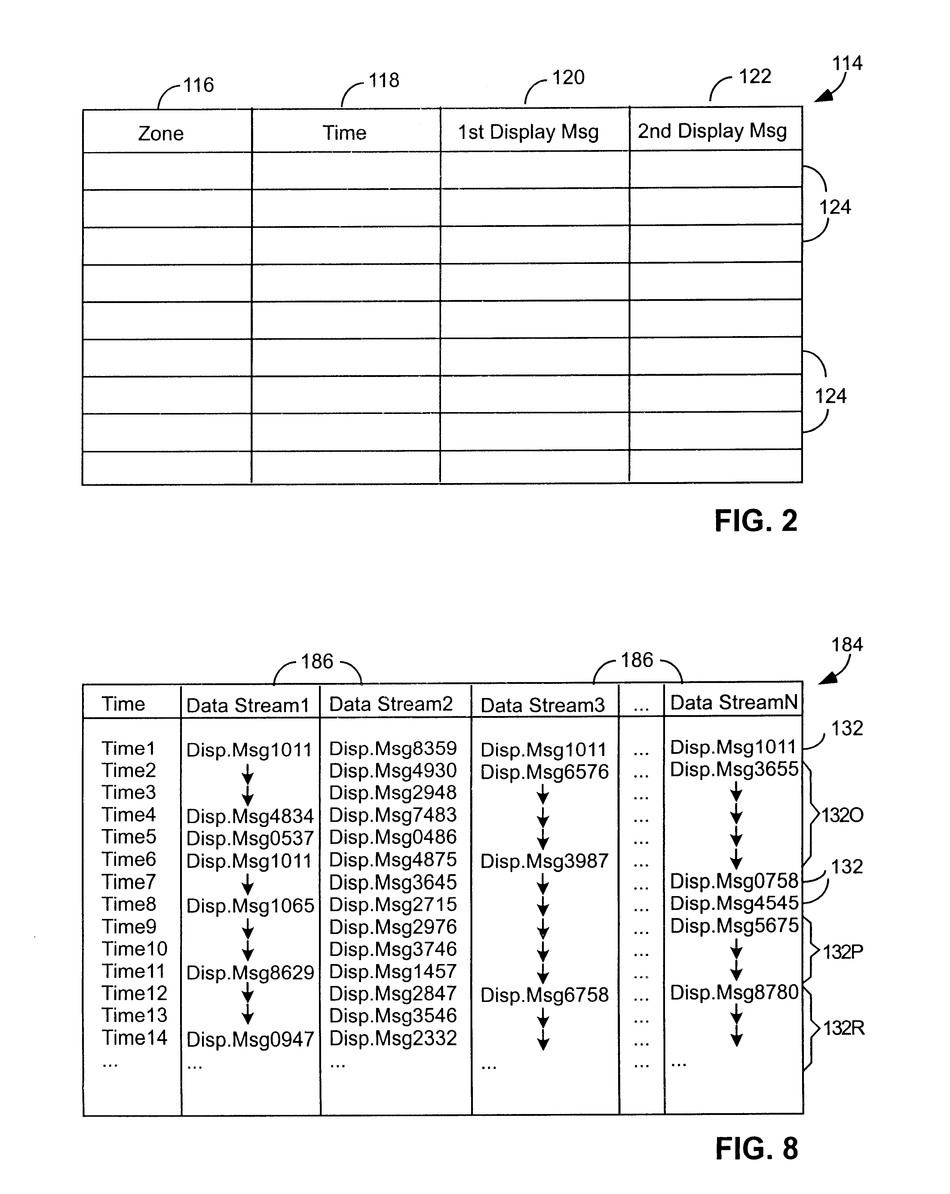
FIG. 1 provides a schematic overview of a system 100 for displaying information on mobile signs according to one embodiment of the present invention. The system 100 includes a central system 102 and one or more mobile units 104 that are controlled by the central system. The central system includes a processor 106 which includes memory 108 that stores programming to control its operation. The processor's memory also includes geographic zone definitions 112 which define the geographic zones in which the system can display different messages. In different implementations geographic zones can be defined differently. In some embodiments they can correspond to zip code or census blocks. In other embodiments they can correspond to the length of a given street along a given block. In some embodiments, zone definitions will tend to remain relatively fixed overtime. In other embodiments zone definitions could be redefined frequently, such as daily, or even hourly, to reflect different geograp...


PUM


Abstract

A system for publicly displaying messages includes elements carried by an automotive vehicle. In some embodiments the vehicle carries a publicly visible electronic display; a sensor for sensing the brightness of light in the vicinity of the display; and illumination varying circuitry for varying the brightness of light generated by the display in response to brightness detected by the sensor. In some embodiments the vehicles carries a publicly visible display formed by ganging together a plurality of displays, each having at least 640×480 pixels; and video drive circuitry for causing images to be shown on the ganged display with different portions of individual images being shown on each of the individual displays. In some embodiments the vehicle has an automotive electrical system and carries a publicly visible high-bright display, capable of providing over 1000 NITS illumination and having 640 by 480 or greater pixel resolution; and video drive circuitry causing images to be shown on the display. In some embodiments the vehicle carries a publicly visible electronic display and a computer. The computer has video drive circuitry for causing images to be shown on the display, a memory device capable of storing representations of animated display images represented in vector-based form; and programming for enabling the computer to generate animated images from the vector-based animation representations. In some embodiments the vehicle receives commands and / or information controlling what it is to display via a wireless transceiver.

Description

All of these related applications are hereby incorporated by reference in their entirety.FIELD OF THE INVENTIONThe present invention relates to a system for displaying information to the public.BACKGROUND OF THE INVENTIONCommunication of information to the public is a major industry. One of the major means of such communications is by publicly visible signs, including advertising signs. Signs have been in use for centuries, and have performed a valuable service of informing consumers about choices that are available to them. But advances in technology have made traditional signs seem somewhat out of date.U.S. Pat. No. 6,060,993 issued to Eyal Cohen (the “Cohen Patent”) discloses one possible system for displaying messages in advertisements on mobile signs, such as those placed on the tops of motor vehicles such as taxis. In this system a geographic area is divided up into separate zones and when a mobile unit makes a transition from one zone into another the controller located on th...

Claims


Application Information

Patent Timeline
IPC IPC(8): B60Q1/26G09F21/00G09F21/04B60Q1/50
CPCB60Q1/2611G09F21/04B60Q1/50G09F21/042B60Q1/5037B60Q1/545
Inventor MANKINS, MATT W. D.HARKAVY, BRADPLATSIDAKIS, MICHAELWHITON, ADAM M.
Owner VERT INC
Learn More