
Method and apparatus for calibrating a linear variable differential transformer

a technology of differential transformer and linear variable, applied in the field of transformer calibration methods and apparatuses, can solve problems such as affecting the validity of the output voltage of the transformer, and achieve the effect of more reliabl

Inactive Publication Date: 2005-01-18
THE UNITED STATES AS REPRESENTED BY THE DEPARTMENT OF ENERGY
View PDF4 Cites 21 Cited by
  • Summary
  • Abstract
  • Description
  • Claims
  • Application Information

AI Technical Summary

Benefits of technology

It is an object of the present invention to overcome the deficiencies of the prior art. It is another object of the present invention to provide a method and apparatus for calibrating an LVDT over a varying temperature range. It is another object of the present invention to provide a method and apparatus for obtaining a valid calibration curve at the precise temperature to which the LVDT will be exposed in working conditions. It is yet another object of the present invention to provide a calibration apparatus that is portable and / or handheld. It is yet another object of the present invention to provide a calibration apparatus that may be utilized in the test assembly, such that the associated instrumentation systems being used for testing can be incorporated into the calibration process, thereby making the resulting test data more reliable.
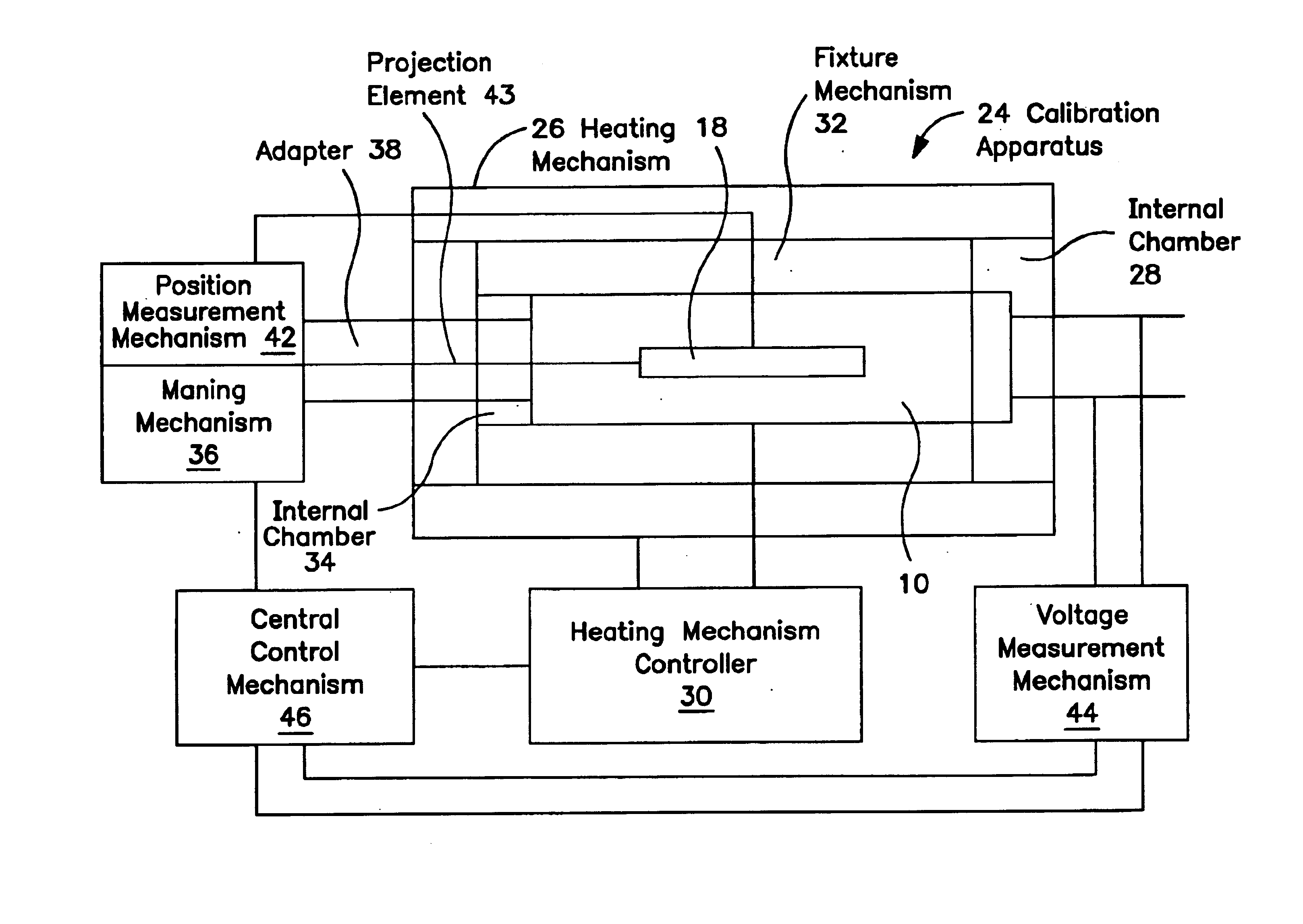
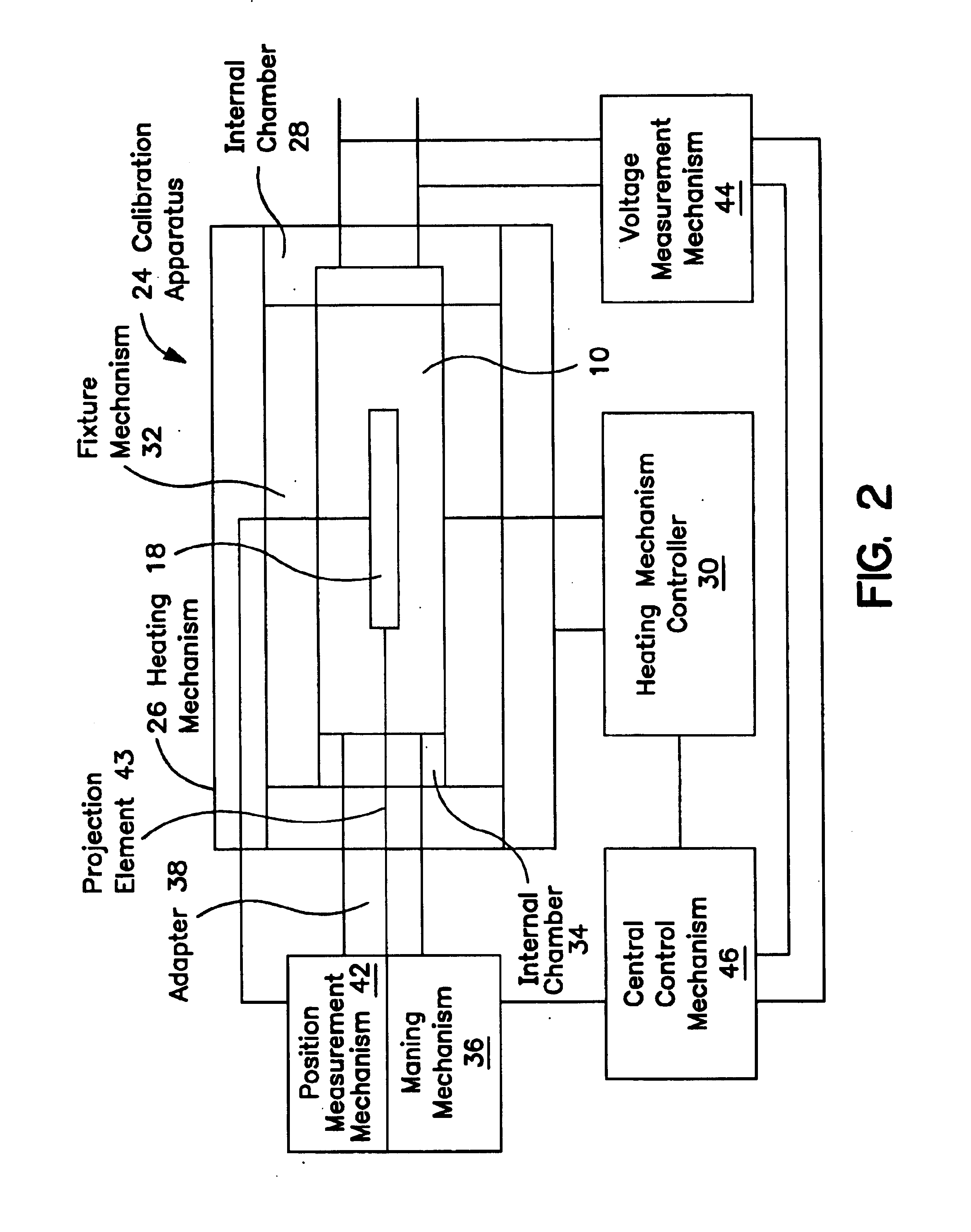
The present invention is a method and apparatus for calibrating a linear variable differential transformer. The present invention is directed to a calibration apparatus for calibrating an LVDT, where the LVDT has an armature positioned in an LVDT armature orifice. This armature or core is configured to move along an axis of movement. The calibration apparatus includes a heating mechanism having an internal chamber, a mechanism for measuring the temperature of the LVDT, and a fixture mechanism with an internal chamber configured to partially accept the LVDT. The fixture mechanism allows the LVDT to be securely positioned within the heating mechanism internal chamber. The calibration apparatus also includes a mechanism for moving the armature along the axis of movement, a mechanism for measuring the position of the armature with respect to the LVDT armature orifice, and a mechanism configured to measure an output voltage from the LVDT.

Problems solved by technology

Any significant change in its test environment temperature will affect the validity of its output voltage.

Method used


Image

  • Method and apparatus for calibrating a linear variable differential transformer
  • Method and apparatus for calibrating a linear variable differential transformer
  • Method and apparatus for calibrating a linear variable differential transformer

Examples


Embodiment Construction

FIG. 1 illustrates a linear variable differential transformer (LVDT) 10 according to the present invention. As seen in FIG. 1, the LVDT 10 includes a primary coil 12 and at least two secondary coils 14. The primary coil 12, as well as the secondary coils 14, are typically tubular in construction, and the primary coil 12 is located centrally and is surrounded by the secondary coils 14. Due to the tubular construction of the primary coil 12 and the secondary coils 14, an armature orifice 16 is created.

Located within the armature orifice 16 is an armature 18, which is adapted to move axially through the armature orifice 16 along an axis of movement. An input voltage is applied to the primary coil 12 via an input voltage lead 20. Similarly, the resulting alternating voltage or output voltage is produced by the secondary coils 14 and is transmitted through output voltage leads 22.

As the armature 18 is moved along the armature orifice 16, the varying magnetic field induces a varying outpu...


PUM


Abstract

A calibration apparatus for calibrating a linear variable differential transformer (LVDT) having an armature positioned in au LVDT armature orifice, and the armature able to move along an axis of movement. The calibration apparatus includes a heating mechanism with an internal chamber, a temperature measuring mechanism for measuring the temperature of the LVDT, a fixture mechanism with an internal chamber for at least partially accepting the LVDT and for securing the LVDT within the heating mechanism internal chamber, a moving mechanism for moving the armature, a position measurement mechanism for measuring the position of the armature, and an output voltage measurement mechanism. A method for calibrating an LVDT, including the steps of: powering the LVDT; heating the LVDT to a desired temperature; measuring the position of the armature with respect to the armature orifice; and measuring the output voltage of the LVDT.

Description

BACKGROUND OF THE INVENTION1. Field of the InventionThe present invention relates generally to calibration techniques and apparatus for transformers and, in particular, to a method and apparatus for calibrating a linear variable differential transformer.2. Description of Related ArtA linear variable differential transformer (LVDT) is a mutual inductance device (transformer) that produces an electrical output proportional to the displacement of a moveable core. Like other transformers, an LVDT consists of a primary coil, secondary coils (typically two), and a magnetic core or armature. An alternating current carrier excitation is applied to the primary winding or coil. It is this current in the primary coil that produces a varying magnetic field around the armature. The two secondary windings or coils are symmetrically spaced from the primary coil and are connected in a series opposing circuit. The magnetic field produced by the primary coil induces an alternating voltage in the seco...

Claims


Application Information

Patent Timeline
IPC IPC(8): G01D5/22G01D5/12G01D18/00
CPCG01D18/00G01D5/2291
Inventor POKRYWKA, ROBERT J.
Owner THE UNITED STATES AS REPRESENTED BY THE DEPARTMENT OF ENERGY
Learn More