
Tricycle with geared auxiliary steering mechanism

a technology of auxiliary steering mechanism and tricycle, which is applied in the direction of steering device, cycle equipment, carriage/perambulator with multiple axes, etc., can solve the problems of back pain and injuries, complex arrangement, and exposure to potential damag

Active Publication Date: 2005-01-11
RADIO FLYER
View PDF10 Cites 36 Cited by
  • Summary
  • Abstract
  • Description
  • Claims
  • Application Information

AI Technical Summary

Benefits of technology

The present invention is directed to a tricycle featuring an auxiliary steering mechanism. The tricycle features a hollow main frame member to which a seat and a pair of rear wheels are mounted. A head tube is also attached to the main frame member and a front wheel and handlebars are mounted to a post which is pivotally mounted within the head tube.

Problems solved by technology

Inconvenience at best and back pain and injuries at worst may result if an adult is required to bend over and grasp the handlebars from behind the tricycle.
A disadvantage of the tricycle of the Li '713 and '048 patents, however, is that the external location of the rods connecting the push handle pivot link to the front fork exposes them to potential damage such as bending.
In addition, the arrangement is complex from the standpoint that there are pivot connections between the ends of each rod and the handlebar bracket and push handle pivot link.
Each such pivot connection requires hardware such as nuts and bolts and is a point of wear.
Although the belt-drive arrangement of the Wu '598 patent may be concealed within a frame cover so as to not be exposed, the belt is subject to wear and could stretch and require replacement.
This could be a time-consuming chore and inconvenience.
In addition, durability is a concern as the teeth on the inner surface of the belt could break or wear off or the belt could skip teeth on the gears as it stretches and wears.

Method used


Image

  • Tricycle with geared auxiliary steering mechanism
  • Tricycle with geared auxiliary steering mechanism
  • Tricycle with geared auxiliary steering mechanism

Examples


Embodiment Construction

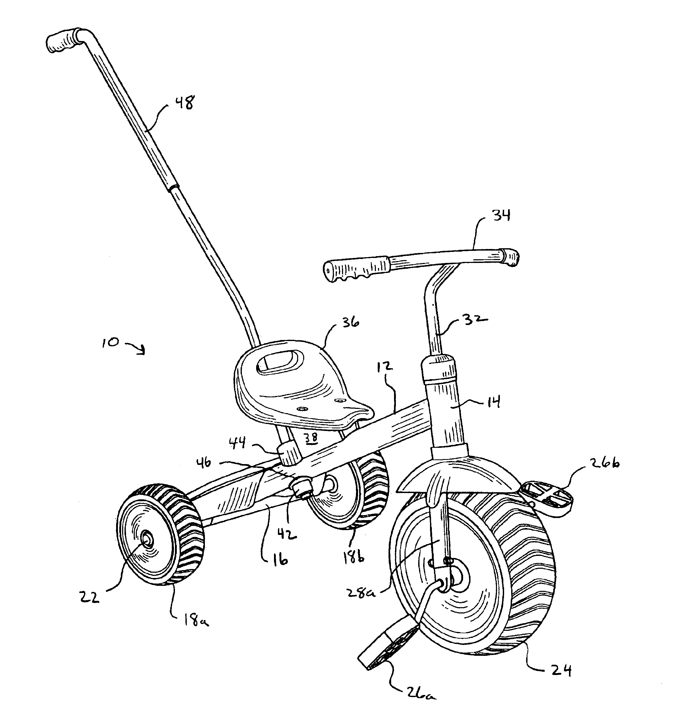
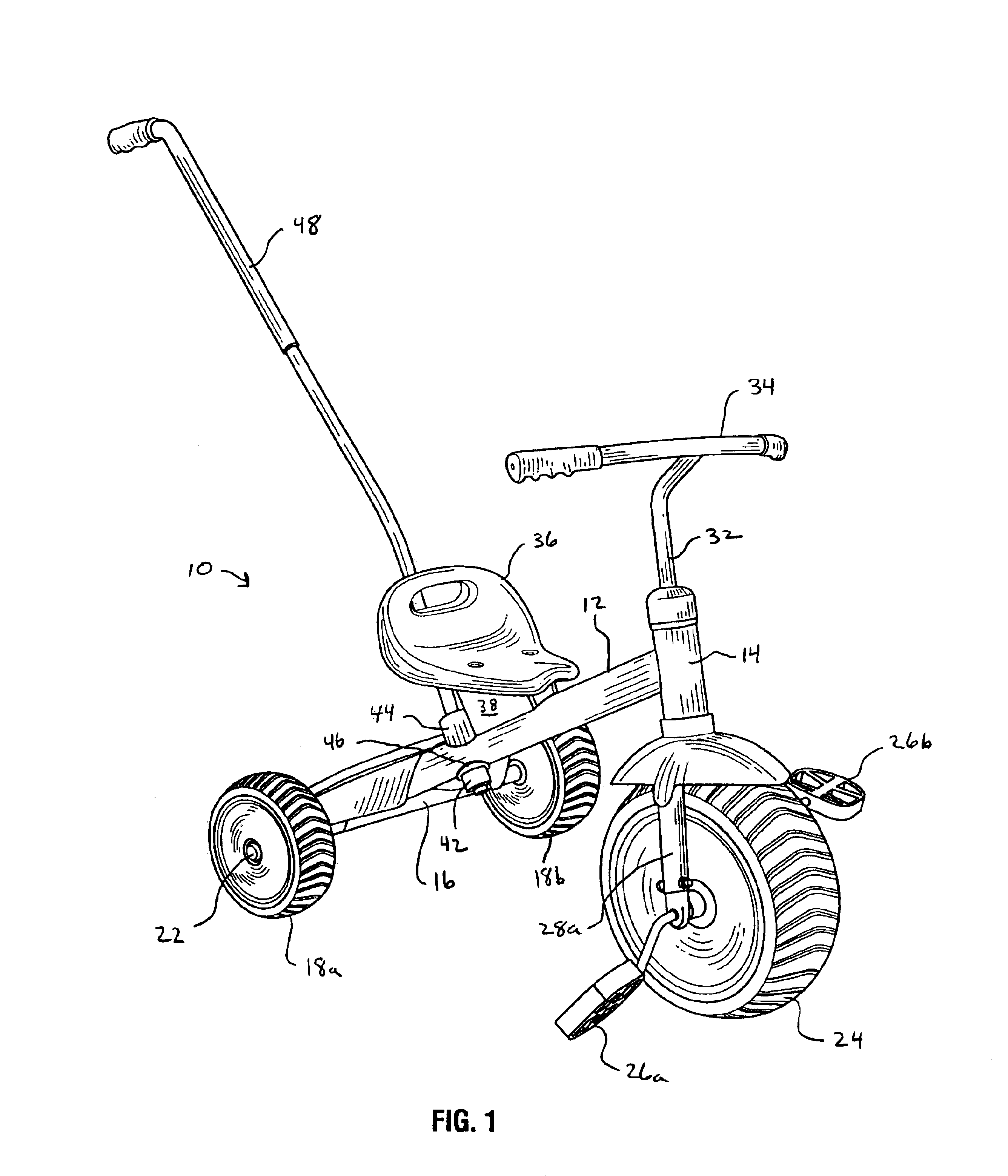
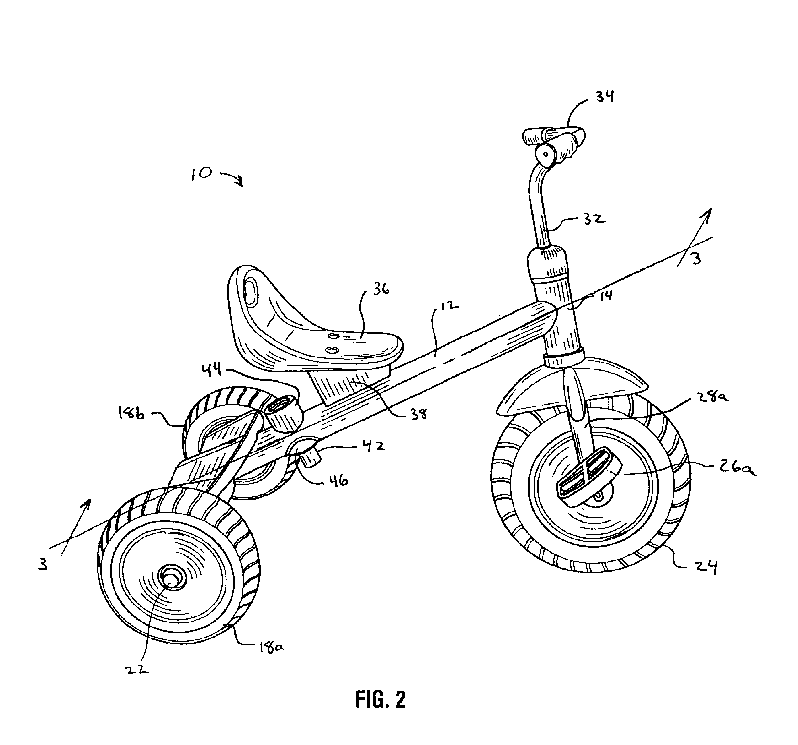
An embodiment of the tricycle of the present invention is indicated in general at 10 in FIGS. 1 and 2. The tricycle features a hollow main frame member 12. A head tube 14 is attached to the leading end of the frame member 12. An axle tube, illustrated at 16 in FIG. 1, is attached to the trailing end of frame member 12. A pair of rear wheels 18a and 18b are mounted upon an axle 22 that passes through axle tube 16. The tricycle also features a front wheel 24 having pedals 26a and 26b attached thereto. The front wheel is mounted between a pair of front fork members 28a and 28b (28b not visible in FIGS. 1 and 2), which are attached to the bottom end of a post 32. Handlebars 34 are attached to the top end of the post. The post 32 is pivotally mounted within the head tube 14 so that the tricycle may be steered by handlebars 34. A seat 36 is mounted upon the frame member 12 by seat bracket 38. The frame, head tube, rear axle tube, post and front forks are preferably made of steel.

As also i...


PUM


Abstract

A tricycle features a hollow main frame member to which a pair of rear wheels and a seat are mounted. A head tube is attached to the main frame member and a post is pivotally positioned therein. The tricycle front wheel is connected to the lower end of the post while handlebars are connected to the upper end of the post. A steering miter gear is also attached to the post within the head tube. A steering shaft is rotatably positioned with the hollow main frame member and features miter gears on its leading and trailing ends. The miter gear on the leading end engages the steering miter gear while the miter gear on the trailing end engages a miter gear that is removably engaged by a pushing and steering handle. The tricycle thus may be pushed and steered by the handle.

Description

BACKGROUND OF THE INVENTIONThe present invention relates generally to tricycles for children and, more particularly, to a tricycle for children featuring a geared auxiliary steering mechanism.Tricycles have long been a popular type of riding vehicle for children. A tricycle features a front wheel that is equipped with pedals and a pair of rear wheels that are spaced apart and joined to the front wheel by a frame. A seat is typically mounted to the frame as is a head tube that receives a post. The front wheel is attached to the bottom of the post via a fork. Handlebars are attached to the top end of the post and the post pivots about its longitudinal axis within the head tube. As a result, the tricycle may be steered by the handlebars.Tricycles featuring push handles have become popular in the marketplace. The push handles are typically attached to the tricycle frame behind the seat and in front of the rear wheels in a removable fashion and extend up and rearwards for easy gripping b...

Claims


Application Information

Patent Timeline
IPC IPC(8): B62K9/02B62K21/00B62H7/00B62K9/00B62J27/00
CPCB62H7/00B62K21/00B62K9/02
Inventor MICHELAU, FREDERICKSCHLEGEL, THOMAS
Owner RADIO FLYER
Learn More