Distortion cancellation for RF amplifiers using complementary biasing circuitry

a biasing circuit and distortion cancellation technology, applied in the field of nonlinear devices, can solve the problems of reducing the size, complexity and cost of the overall amplification system, operating a linear amplifier at a back off power level, and affecting the signal quality of the signal

Inactive Publication Date: 2004-12-14
QORVO US INC
View PDF6 Cites 25 Cited by
  • Summary
  • Abstract
  • Description
  • Claims
  • Application Information

AI Technical Summary

Problems solved by technology

On the other hand, a non-linear amplifier causes degradation of signal quality due to amplitude and phase distortions caused by nonlinear devices.
Thus, usage of linear amplifiers directly results in reducing size, complexity and cost of the overall amplification systems which is highly important in applications such as satellite systems and cellular base stations.
However, operating a linear amplifier at a back off power level has its own drawbacks.
Indeed, the tradeoff of operating a linear amplifier at a back off power level is a low DC-to-RF efficiency on the amplifiers since peak DC-to-RF efficiency is usually achieved near a saturated output power level.
However, conventional linearization techniques require the use of external circuitry to reduce distortion levels at the output of non-linear amplifiers.
These techniques, however, usually involve very complex circuit configurations and require extensive alignment in production.
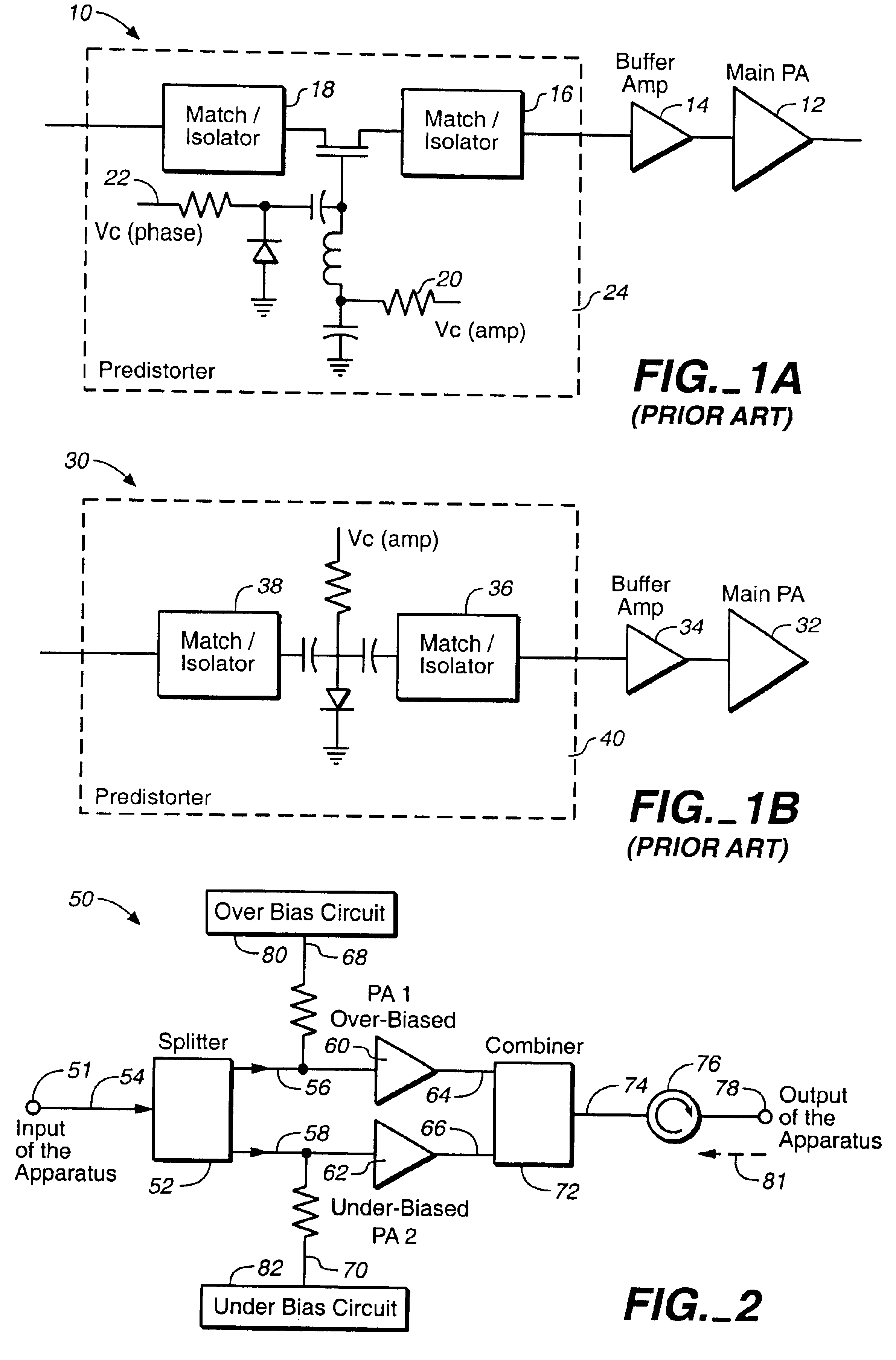
In addition, these prior art predistortion schemes (10 of FIG. 1A and 30 of FIG. 1B) are difficult to use because they have poor isolation.
Indeed, since conventional predistorters usually experience poor reverse isolation, power amplifiers incorporating the predistorters require additional isolators to improve circuit isolation to avoid interaction between the predistorters and amplifier stages which would degrade overall circuit performance.
The use of buffer amplifiers is of particular concern as that would increase overall DC power consumption.
Even though the overall efficiency of the linearized amplifier is improved, the increased DC power requirements increase the size and cost of the power supply or battery needed.

Method used


Image

  • Distortion cancellation for RF amplifiers using complementary biasing circuitry
  • Distortion cancellation for RF amplifiers using complementary biasing circuitry
  • Distortion cancellation for RF amplifiers using complementary biasing circuitry

Examples


Embodiment Construction

Reference will now be made in detail to the preferred embodiments of the invention, examples of which are illustrated in the accompanying drawings. While the invention will be described in conjunction with the preferred embodiments, it will be understood that they are not intended to limit the invention to these embodiments. On the contrary, the invention is intended to cover alternatives, modifications and equivalents that may be included within the spirit and scope of the invention as defined by the appended claims. Furthermore, in the following detailed description of the present invention, numerous specific details are set forth in order to provide a thorough understanding of the present invention. However, it will be obvious to one of ordinary skill in the art that the present invention may be practiced without these specific details. In other instances, well known methods, procedures, components, and circuits have not been described in detail as not to unnecessarily obscure as...


PUM


Abstract

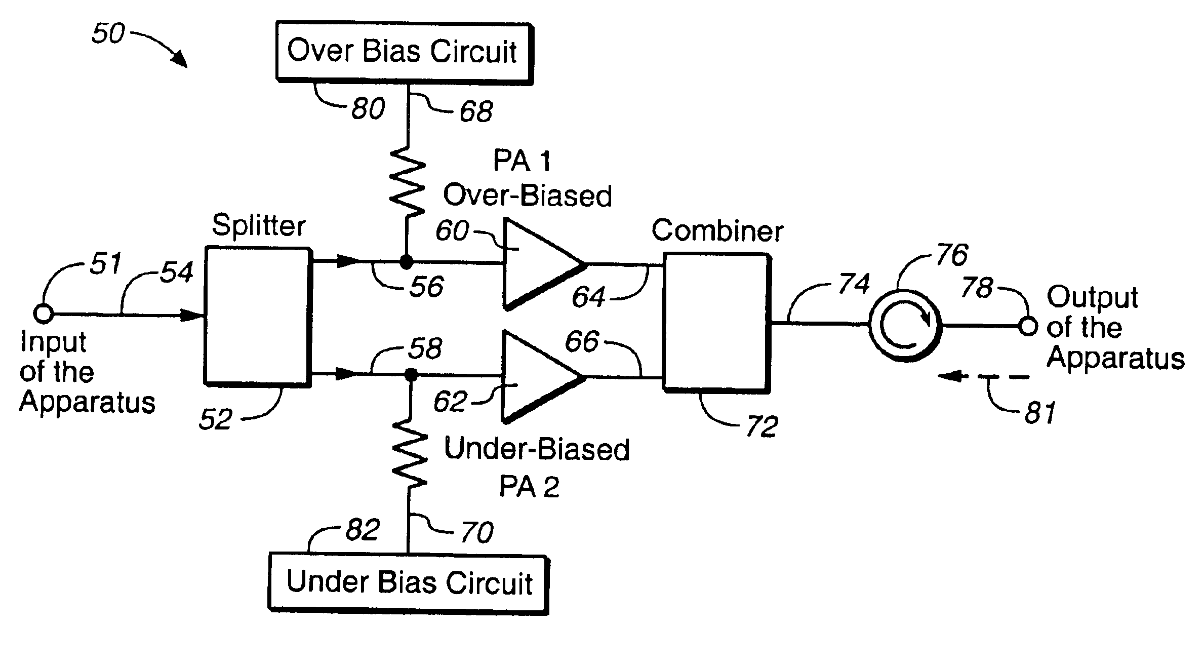
An apparatus for improving linearity of an RF signal comprising: (a) a splitter configured to receive an input RF signal, and configured to split the input RF signal into two RF signals comprising a first input RF signal, and a second input RF signal; (b) an over-biased non-linear RF power amplifier configured to receive the first input RF signal and configured to generate an over-biased non-linear output signal having an over-biased non-linear distortion component; (c) an under-biased non-linear RF power amplifier configured to receive the second input RF signal and configured to generate an under-biased non-linear output signal having an under-biased non-linear distortion component; and (d) a combiner configured to combine the over-biased non-linear output signal and the under-biased non-linear output signal, and configured to output the RF signal having substantially cancelled over-biased and under-biased distortion components. The over-biased non-linear RF power amplifier is configured to receive an over-biased DC signal being greater than an optimum bias DC voltage. The under-biased non-linear RF power amplifier is configured to receive an under-biased DC signal being lower than the optimum bias DC voltage.

Description

1. Field of the InventionThe present invention is in the field of nonlinear devices, and more specifically, is in the field of reducing distortion produced by nonlinear devices.2. Discussion of the Prior ArtIn the prior art, digital modulation schemes are widely employed in various multi-carrier communication systems (for instance, in wireless communication systems, in satellite communication systems, etc.) to achieve multiple objectives, like capacity improvement, better transmitted quality of data, and higher data rate transmission. In non-constant envelope digital modulation schemes, the information is included in both amplitude and phase of the modulated signals.In the prior art, a linear amplifier is a preferable device to amplify such signals, because, in theory, an ideal linear amplifier does not cause signal distortions. On the other hand, a non-linear amplifier causes degradation of signal quality due to amplitude and phase distortions caused by nonlinear devices. In additi...

Claims


Application Information

Patent Timeline
Patent Type & Authority Patents(United States)
IPC IPC(8): H03F3/60H03F1/32H03F1/30
CPCH03F1/30H03F3/602H03F1/32H03F2200/468
Inventor HOLLINGSWORTH, GREGG ALANSHALLAL, KHALID PAULMUELLENBERG, DEAN T.
Owner QORVO US INC
Why Eureka
Try Eureka