
Extended virtual table: an optical extension for table-like projection systems

a projection system and virtual table technology, applied in image data processing, programme control, instruments, etc., can solve the problems of limited application, visual undistorted direct interaction with the virtual scene, and occlusion caused by the user's hand or hand-held input device,

Inactive Publication Date: 2004-10-12
FRAUNHOFER GESELLSCHAFT ZUR FOERDERUNG DER ANGEWANDTEN FORSCHUNG EV
View PDF9 Cites 141 Cited by
  • Summary
  • Abstract
  • Description
  • Claims
  • Application Information

AI Technical Summary

Benefits of technology

The patent text describes a new technology for combining virtual and augmented real environments in a way that allows for seamless integration in the workplace. The technology uses a combination of mirror beam-splitters and table-like projection systems to create a more immersive experience for the user. The main advantage of this technology is that it allows for spatially augmented reality, where virtual and real objects can coexist in the same space. The patent also discusses the limitations of current display technology and proposes a solution to overcome them. Overall, the technology provides a cost-effective and simple-to-realize solution for creating seamless augmented realities in the workplace.

Problems solved by technology

As for stereoscopic screen-based desktop systems, occlusion caused by the user's hand or hand-held input devices is a main drawback of table-like rear-projection systems.
This disadvantage makes a visually undistorted direct interaction with the presented virtual scene difficult--especially if force-feedback devices such as a PHANTOM (Massie & Salisbury, 1994), etc., are applied to superimpose virtual visual and virtual haptic spaces.
Due to the small working volume of these devices, their applications are limited to near-field operations.

Method used


Image

  • Extended virtual table: an optical extension for table-like projection systems
  • Extended virtual table: an optical extension for table-like projection systems
  • Extended virtual table: an optical extension for table-like projection systems

Examples


Embodiment Construction

of the Virtual Table

Hardware

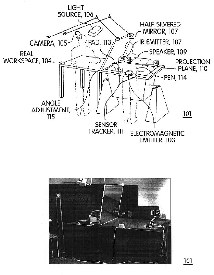
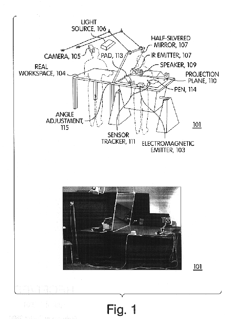
A preferred embodiment of system 1301 uses the Baron Virtual Table produced by the Barco Group as its display device. This device offers a 53".times.40" display screen built into a table surface. The display is produced by a Indigo2.TM. Maximum Impact workstation manufactured by Silicon Graphics, Incorporated. When the display is viewed through CrystalEyes.RTM. shutter glasses from StereoGraphics Corporation, the result is a virtual environment of very high brightness and contrast. The shutter glasses in the preferred embodiment are equipped with 6DOF (six degrees of freedom) Flock of Birds.RTM. trackers made by Ascension Technology Corporation for position and orientation tracking.

Software

Software architecture: In the preferred embodiment, virtual reality system program 1309 is based on the Studierstube software framework described in D. Schmalstieg, A. Fuhrmann, Z. Szalavari, M. Gervautz: "Studierstube"--An Environment for Collaboration in Augmented Rea...


PUM


Abstract

Apparatus that uses a large transflective mirror to extend a virtual reality system such as a virtual table that employs a projection plane to produce the virtual reality. The transflexive mirror is positioned relative to the projection plane such that the plane of the mirror intersects the projection plane and the angle of the mirror relative to the projection plane is such that the user of the system who looks at the mirror sees the projection plane reflected in the mirror. The virtual reality system is responsive to the position of the mirror and the direction in which a user is looking and produces separate virtual realities on the projection plane: one when the user is looking at the mirror and another when the user is looking at the projection plane. The virtual reality that the user sees when looking at the mirror may or may not be coherent with the virtual reality that the user sees when looking at the projection plane. The two virtual realities may share a global coordinate system that is divided into two parts by the plane of the mirror, and what the user sees when looking into the mirror may be what the user would see looking through a window into the part of the global coordinate system behind the mirror. Because the mirror is transflective, real objects whose locations are known to the virtual reality system can he placed behind the mirror and the virtual reality reflected in the mirror may be used to augment the real objects. One use of such augmentation is virtual trial assembly of a virtual mockup with a physical mockup.

Description

1. Field of the InventionThe invention relates generally to virtual and augmented environments and more specifically to the application of mirror beam-splitters as optical combiners in combination with table-like projection systems that are used to visualize such environments.2. BackgroundVirtual Reality (VR) attempts to provide a sense of spatial presence (visual, auditory, or tactile) inside computer-generated synthetic environments to the user. Opaque head-mounted displays (HMDs) and surround-screen (spatially immersive) displays such as CAVEs, (Cruz-Neira, Sandin & DeFanti, 1993) and domed displays (Bennett, 2000) are VR devices that surround the viewer with graphics by filling a great amount of the user's field of view. To achieve this kind of immersion, however, these devices encapsulate the user from the real world, thus making it in many cases difficult or even impossible to combine them with habitual work environments.Other, less immersive display technology is more promisi...

Claims


Application Information

Patent Timeline
Patent Type & Authority Patents(United States)
IPC IPC(8): G05B19/18G06F3/033G06F3/00G02B27/10G06F3/01G06F3/042
CPCG05B19/186G06F3/033G06F3/0304G06F3/011G05B2219/32014G06F3/012
Inventor BIMBER, OLIVERENCARNACAO, L. MIGUELSTORK, ANDRE
Owner FRAUNHOFER GESELLSCHAFT ZUR FOERDERUNG DER ANGEWANDTEN FORSCHUNG EV
Learn More