
Quick adjusting choke winch

a winch and quick technology, applied in the field of sidethreading winches, can solve the problems of time-consuming adjustment process for removing slack, and the choke to shift and the object being lifted to sift further or fall

Inactive Publication Date: 2004-10-05
ANDERSON TONY D
View PDF6 Cites 35 Cited by
  • Summary
  • Abstract
  • Description
  • Claims
  • Application Information

AI Technical Summary

Problems solved by technology

If the orientation is wrong, the choke strap may not be secured, causing the choke to shift and the object being lifted to sift further or fall.
If a strap is slack or the orientation is wrong then a strap is not carrying the desired proportion of the load.
The adjustment process to remove the slack is time consuming, and often has to be repeated numerous times because it is largely one of an educated guess.
The problem is especially difficult to correct when the object has a complex asymmetrical shape.
The addition of multiple come-alongs also costs, increases the possibility for mechanical failure and therefore poses a safety problem.
Similar problems are encountered, plus a conventional strap winch requires end on threading.

Method used


Image

  • Quick adjusting choke winch
  • Quick adjusting choke winch
  • Quick adjusting choke winch

Examples


Embodiment Construction

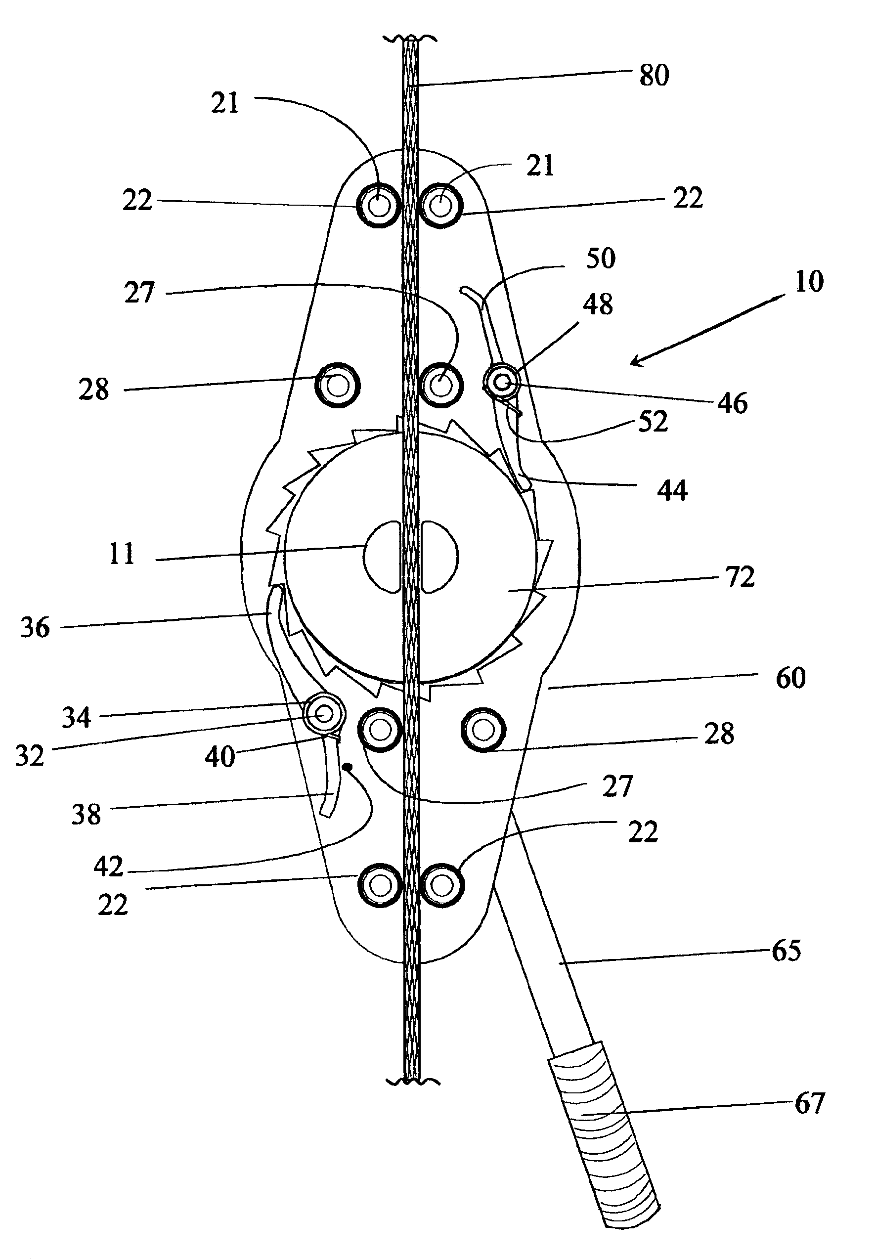
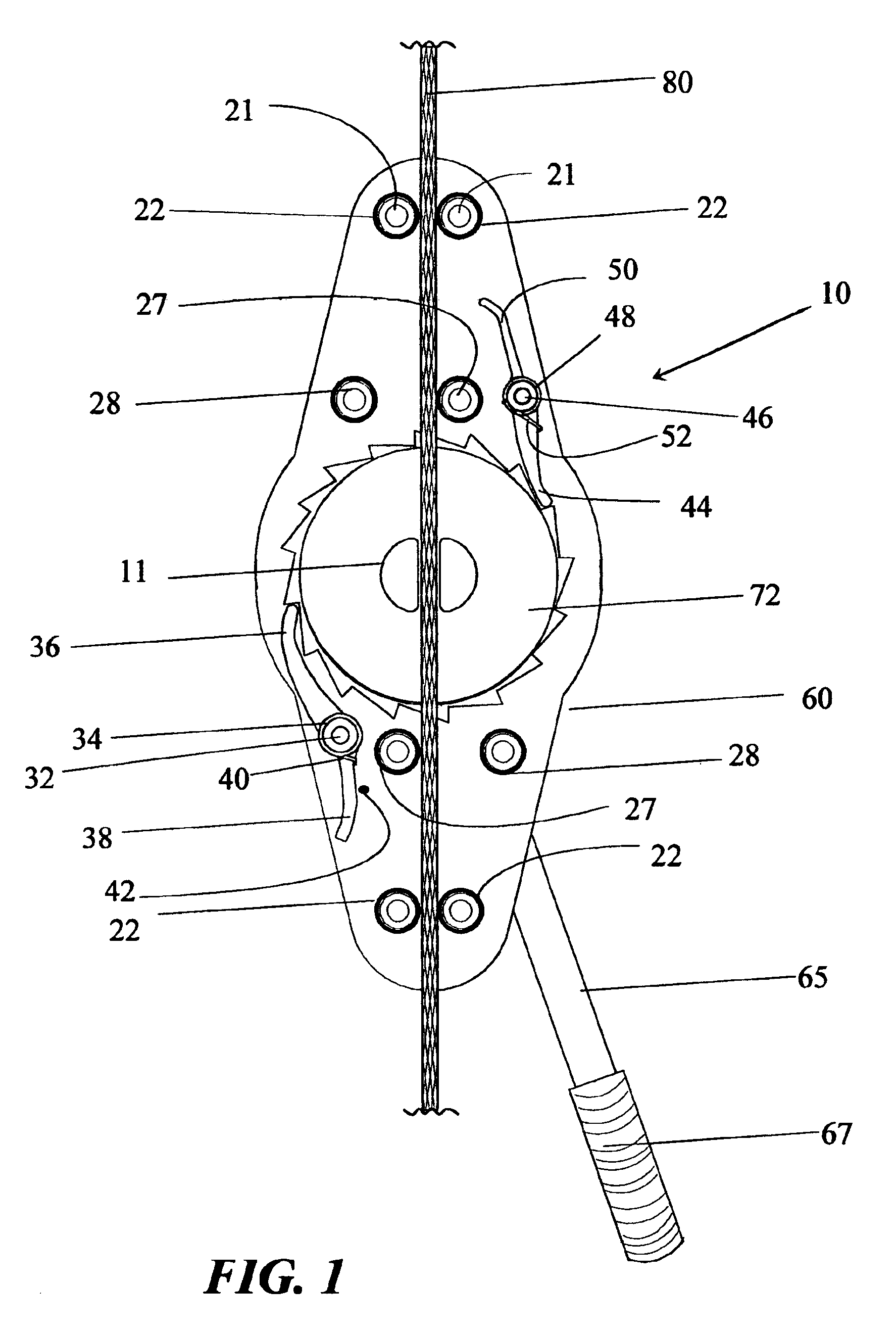
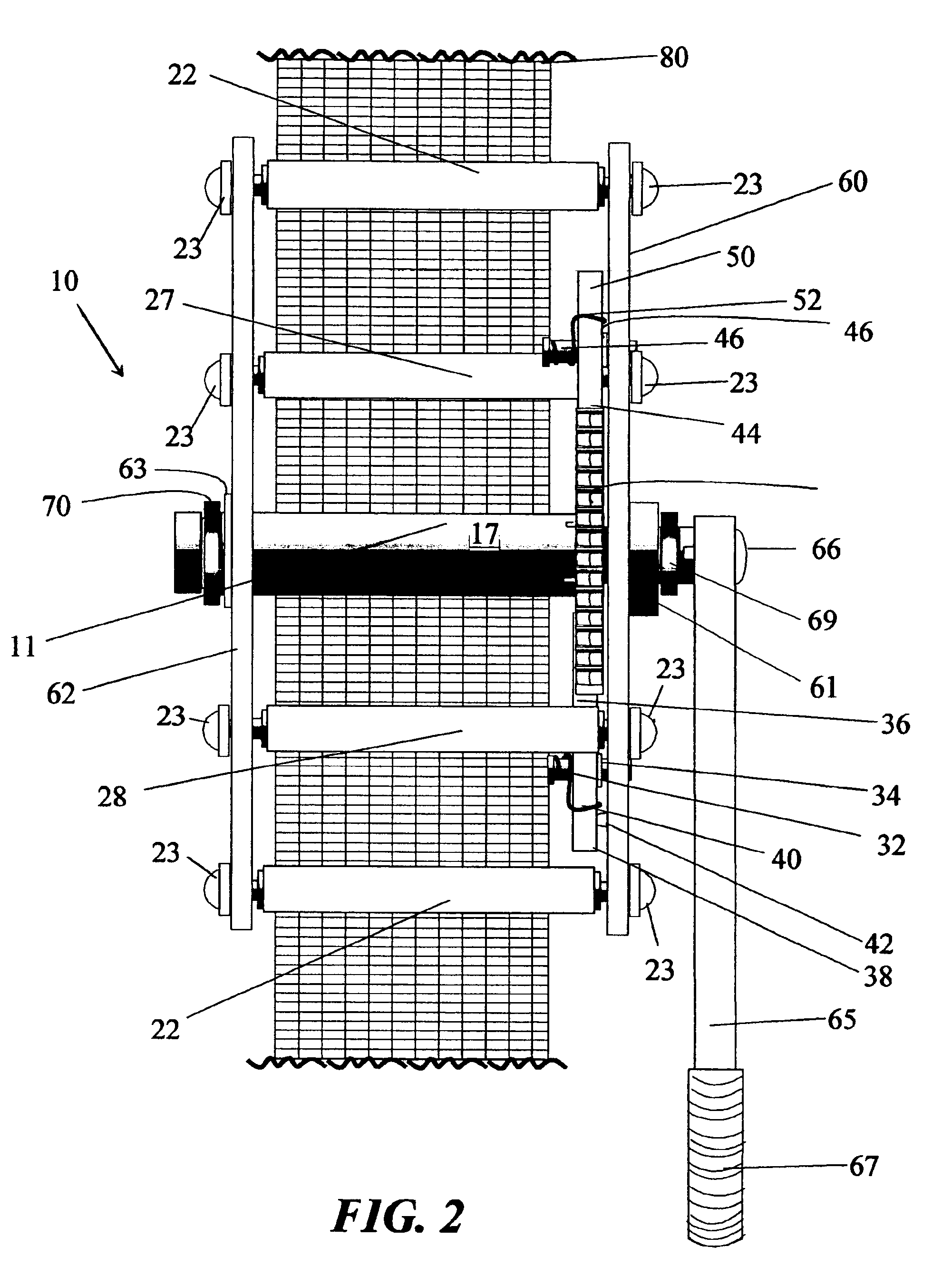
Most of the operational components of the quick adjusting choke winch 10 are shown in FIG. 1. Mounted on an oblong curvilinear base plate 60, which is substantially circular in the center and ellipsoidal lengthwise, therein at the centroid there is an open-ended split-center shaft 11 through which passes a choker strap 80. The open-ended split-center shaft 11 is fitted with a ratchet 72. On opposing sides of the ratchet there are two pack roll, both indicated by 27. The pack rolls, as shown in FIG. 3, establish the tangential angle for the strap as it is wound. Referring again to FIG. 1, there is first pair of rollers 21 and a second pair of rollers 22 located near the radial extremes of the base plate. The pairs of rollers 21 and 22, along with backlash rollers 28, which are also located on opposing sides of the ratchet establish the thread path for the strap 80, and in combination are the means for guiding the choke strap. The backlash rollers additionally provide side-to-side twi...


PUM

PropertyMeasurementUnit
thickaaaaaaaaaa
thickaaaaaaaaaa
thickaaaaaaaaaa

Abstract

The invention is a quick adjusting choke winch, wherein in contrast to a winch where the strap is threaded from an end of the choke strap, the choke strap is side-threaded along a longitudinal edge. The invention is appropriately sized so that multiple width straps can be accommodated. The quick adjusting choke winch is comprised of: a base plate having a bearing; an open-ended split-center shaft; at least two pack rollers for controlling the tangential angle of strap being wound; a means for guiding the choke strap within the winch; a ratchet plate; a releasable main pawl; a releasable safety pawl; a means for turning the open-ended split-center shaft; a cover plate; and at least one fastening element for attaching the cover plate. The ratchet plate is co-axially affixed to the open-ended split-center shaft, so that when the ratchet turns the open-ended split-center shaft turns through the same rotation. Mounted on the same side of the plate are an end of the open-ended split-center shaft, an end of the at least two pack rollers, the means for guiding the strap, an end of the main pintle, and an end of the safety pintle. The cover plate is removably mounted to at least the pack rollers, and receives the open-end of the split-center shaft. The split-center of the open-ended split-center shaft has an opening that is sufficiently wide to receive the thickness of the choke strap.

Description

1) Field of the InventionThe invention relates generally to a winch, and more particularly to a side-threading winch which can be quickly affixed to a choke strap, and tightening the same.2) Prior ArtChoke straps are used by crane operators and the like to attach the crane hook to the object to be lifted. During lifting, the object has a desired orientation. The desired orientation is dependent on a number of possible considerations, including, but not limited to: the size of the space through which the object is to be moved, whether the object being lifted is to be connected to another device having a precise orientation, the levelness of the object being lifted (i.e. a pallet loaded with multiple objects that are only partially secured), and the effectiveness of the choke during the lift. If the orientation is wrong, the choke strap may not be secured, causing the choke to shift and the object being lifted to sift further or fall. The proper positioning and the effective length of...

Claims


Application Information

Patent Timeline
Patent Type & Authority Patents(United States)
IPC IPC(8): B60P7/08B60P7/06
CPCB60P7/083Y10T24/2117Y10T24/2175
Inventor ANDERSON, TONY D.
Owner ANDERSON TONY D
Learn More