Battery compartment for a motorized wheel chair

a motorized wheel chair and battery technology, applied in the field of battery compartments, can solve the problems of troublesome and expensive, time-consuming disassembly of the reinforced plate (75), laborious and therefore exhaustive mounting and disassembly of the battery (74)

Inactive Publication Date: 2004-08-03
MERITS HEALTH PRODS
View PDF12 Cites 20 Cited by
  • Summary
  • Abstract
  • Description
  • Claims
  • Application Information

AI Technical Summary

Problems solved by technology

This kind of motorized wheel chair (70) requires constant removal of the batteries (74) from the bracket (71) especially when the motorized wheel chair (70) is to be folded, such that not only the assembly and disassembly of the reinforced plate (75) are time consuming, but also the mounting and dismounting of the batteries (74) are labor intensive and therefore exhaustive.
This may prove to be troublesome and expensive as the wheel chair user will rely on another person, probably a professional carer, whose time will be used excessively in this operation.
A further disadvantage of the motorized wheel chair is that the parts for securing the overall integrity are easily lost especially when disassembly of the motorized wheel chair is a constant routine.

Method used


Image

  • Battery compartment for a motorized wheel chair
  • Battery compartment for a motorized wheel chair
  • Battery compartment for a motorized wheel chair

Examples


Embodiment Construction

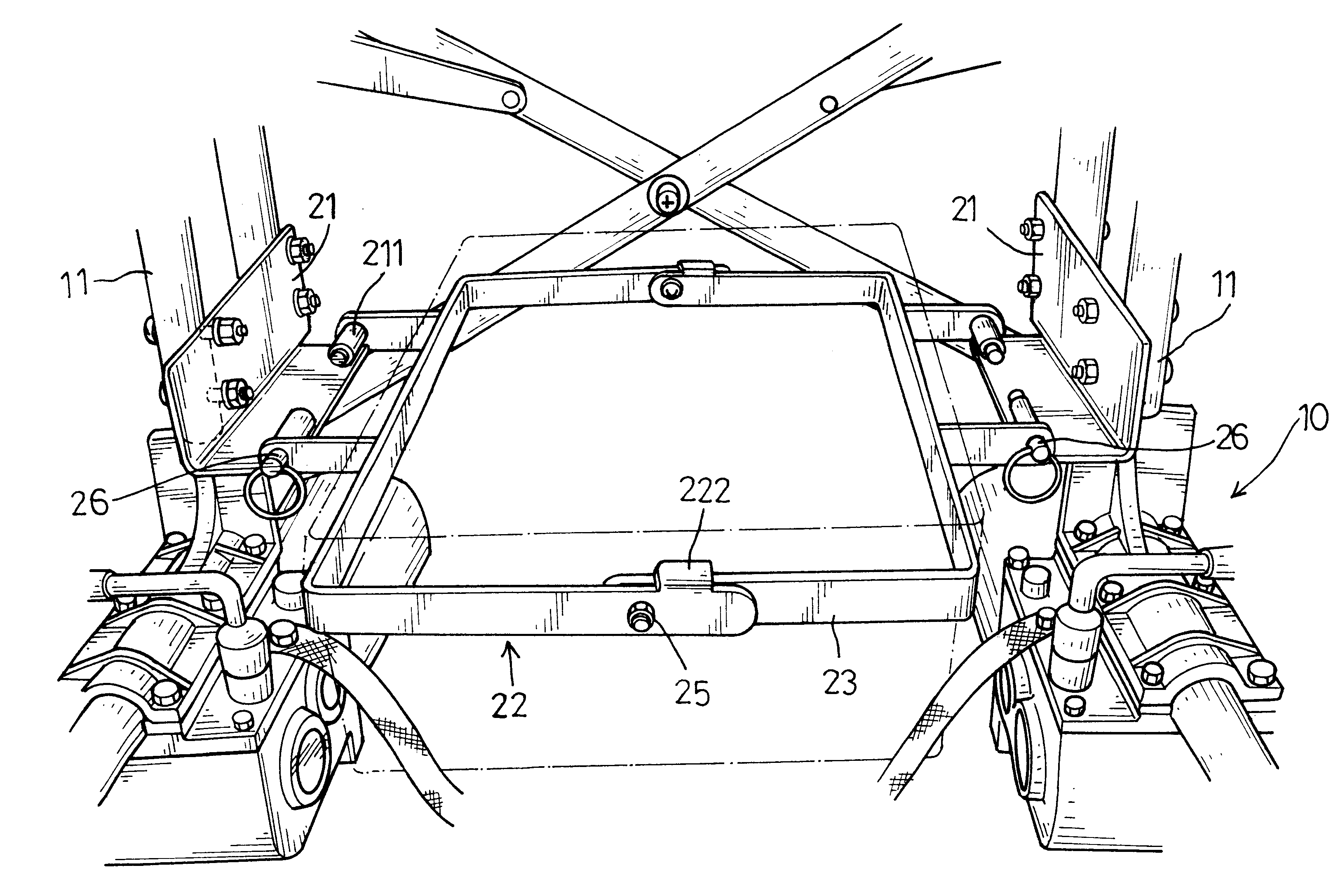
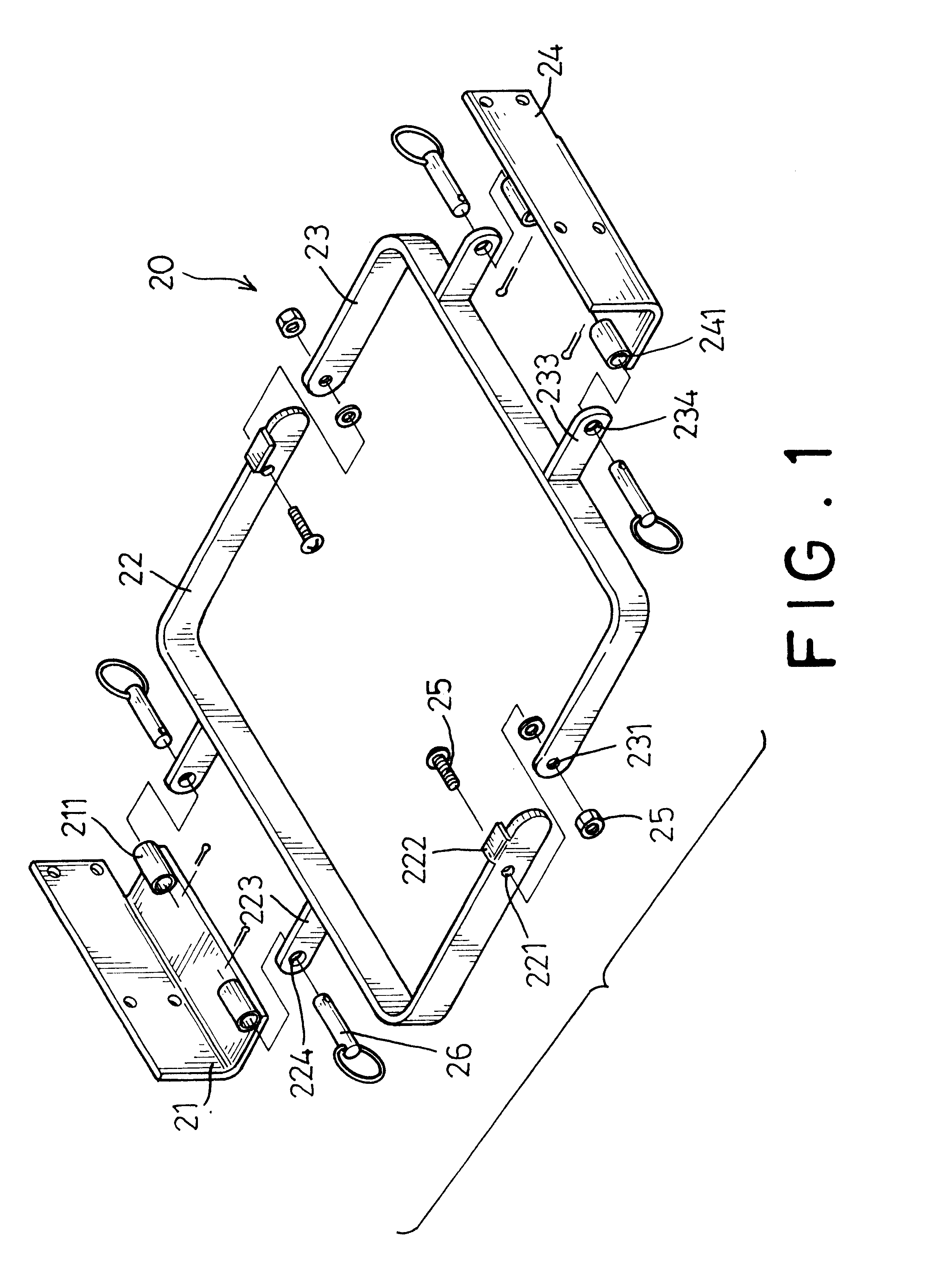
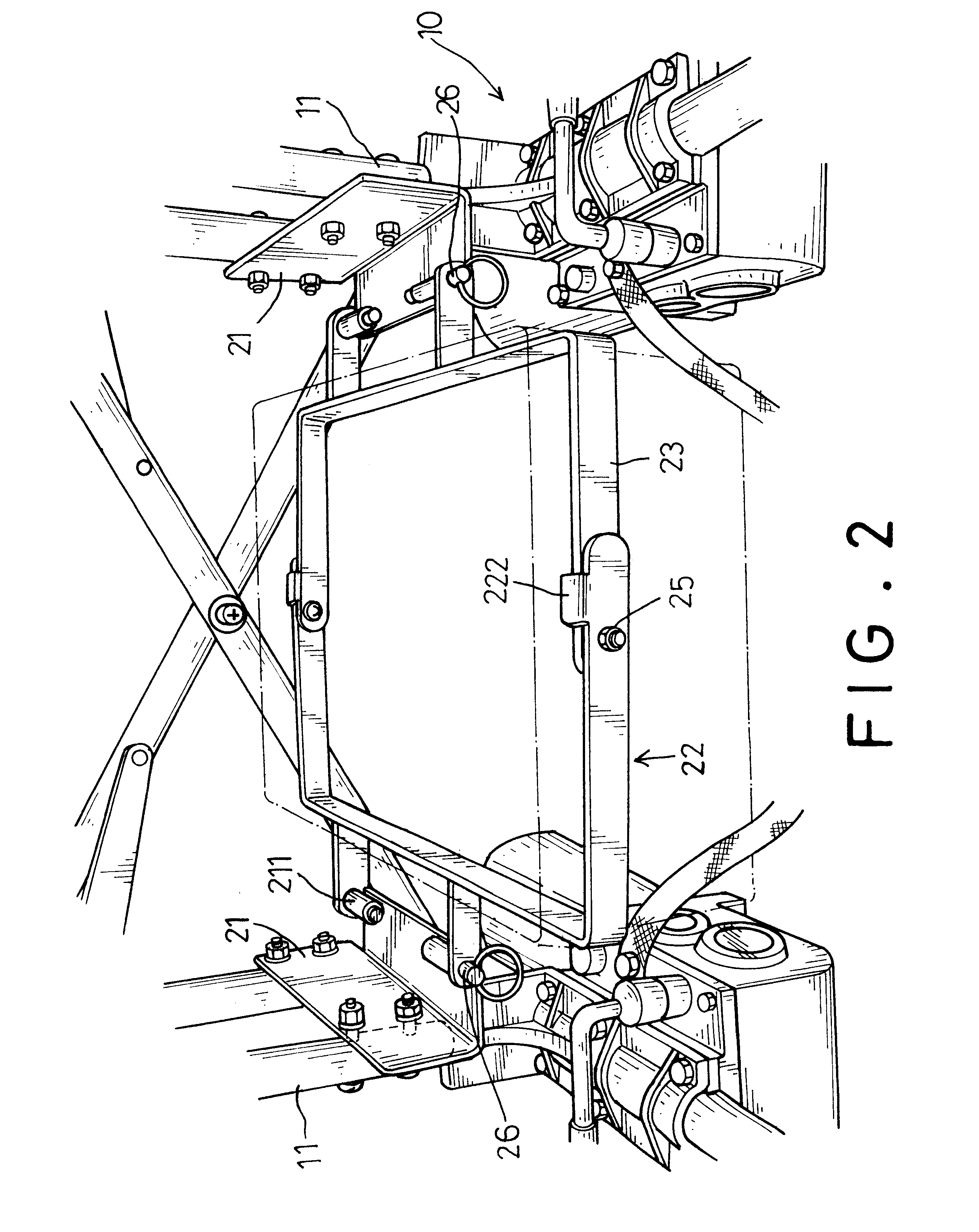
With reference to FIG. 1, the battery compartment (20) has a first securing bracket (21), a first frame (22), a second frame (23) and a second securing bracket (24).

The first securing bracket (21) is L shaped and has a pair of sleeves (211) firmly formed on a horizontal plate of the first securing bracket (21). Because the second securing bracket (24) has the same structure as that of the first securing bracket (21), the description to the second securing bracket (24) is omitted but will be incorporated hereinafter.

The first frame (22) is substantially U shaped and has a hole (221) defined in both distal ends of the first frame (22), a stop (222) formed on a side face adjacent to each of the distal ends of the first frame (22) and extending toward each other, and two first extensions (223) formed on an outer face at a bottom of the first frame (22) and respectively having a through hole (224) defined to correspond to one of the sleeves (211) of the first securing bracket (21).

The se...


PUM


Abstract

A battery compartment for a motorized wheel chair includes a first securing bracket adapted to be securely connected to a side bracket of the motorized wheel chair, and a second securing bracket adapted to be securely connected to the side bracket of the motorized wheel chair and being opposite to the first securing bracket. A U-shaped first frame is pivotally connected to the first securing bracket. A U-shaped second frame is pivotally connected to the second securing bracket and to the first frame.

Description

1. Field of the InventionThe present invention relates to a battery compartment, and more particularly to a battery compartment for a motorized wheel chair. The battery compartment has two halves each pivotally connected with one another and having a stop formed on a side thereof so as to prevent excess pivotal movement of the other.2. Description of Related ArtWith reference to FIG. 4, a conventional motorized wheel chair (60) is shown. The motorized wheel chair (60) has two brackets (61) mounted on opposite sides of the motorized wheel chair (60). The two brackets (61) are connected with connection rods (62) in such a manner that the motorized wheel chair (60) is able to be folded. A battery compartment (63) is formed between two rear wheels (64) so as to receive therein batteries. The batteries are able to provide electricity to power the motor in the motorized wheel chair (60). When the motorized wheel chair (60) is not in use and to be folded, the batteries must be removed and ...

Claims


Application Information

Patent Timeline
Patent Type & Authority Patents(United States)
IPC IPC(8): B60R16/04
CPCB60R16/04Y10S180/907
Inventor CHENG, MING-CHUAN
Owner MERITS HEALTH PRODS
Why Eureka
Try Eureka