Power converter with input-side resonance and pulse-position demodulation feedback control

a power converter and input-side resonance technology, applied in the direction of electric variable regulation, process and machine control, instruments, etc., can solve the problems of inability to distinguish the concept of "development from that deemed ", laborious and unproductive task of describing prior art, and the observations in this document are no longer valid

Inactive Publication Date: 2004-07-27
FIGUEROA SALVADOR
View PDF12 Cites 17 Cited by
  • Summary
  • Abstract
  • Description
  • Claims
  • Application Information

AI Technical Summary

Problems solved by technology

It is extremely difficult to differentiate this conceptual development with that deemed "Prior Art" since the technology described herein is a new and a radically different departure from that in general use at this time.
But to no particular service or advantage to any existing design practice.
Thus, the task of describing the Prior Art becomes laborious and unproductive.
This characteristic was observed but not fully understood until such time it became obvious that attempts to incorporate this feature in the application would invite an objection of "introduction of new matter" by the Examiner.
Observations tendered in this document fortunately are no longer valid, with the development of the anti-resonant topology based on CSAR Technology.
Consequently, current flowing in the parallel tank circuit will develop a voltage of infinite proportion leading to circuit destruction.
In a practical circuit however, this condition is not allowed to exist due to load current reflection from the output winding to the input winding by virtue of both being located on a common magnetic core.
It introduces a situation allowing flow of input current from the input DC voltage source into the anti-resonant circuit due to the power switch being in an ON state beyond this point in time, resulting in the power switch having to interrupt input current and diminished over-all circuit performance.

Method used


Image

  • Power converter with input-side resonance and pulse-position demodulation feedback control
  • Power converter with input-side resonance and pulse-position demodulation feedback control
  • Power converter with input-side resonance and pulse-position demodulation feedback control

Examples


Embodiment Construction

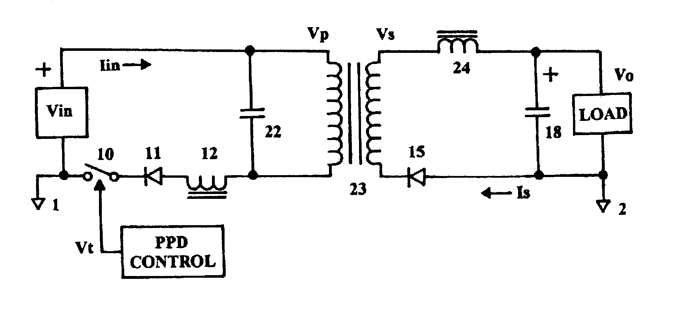
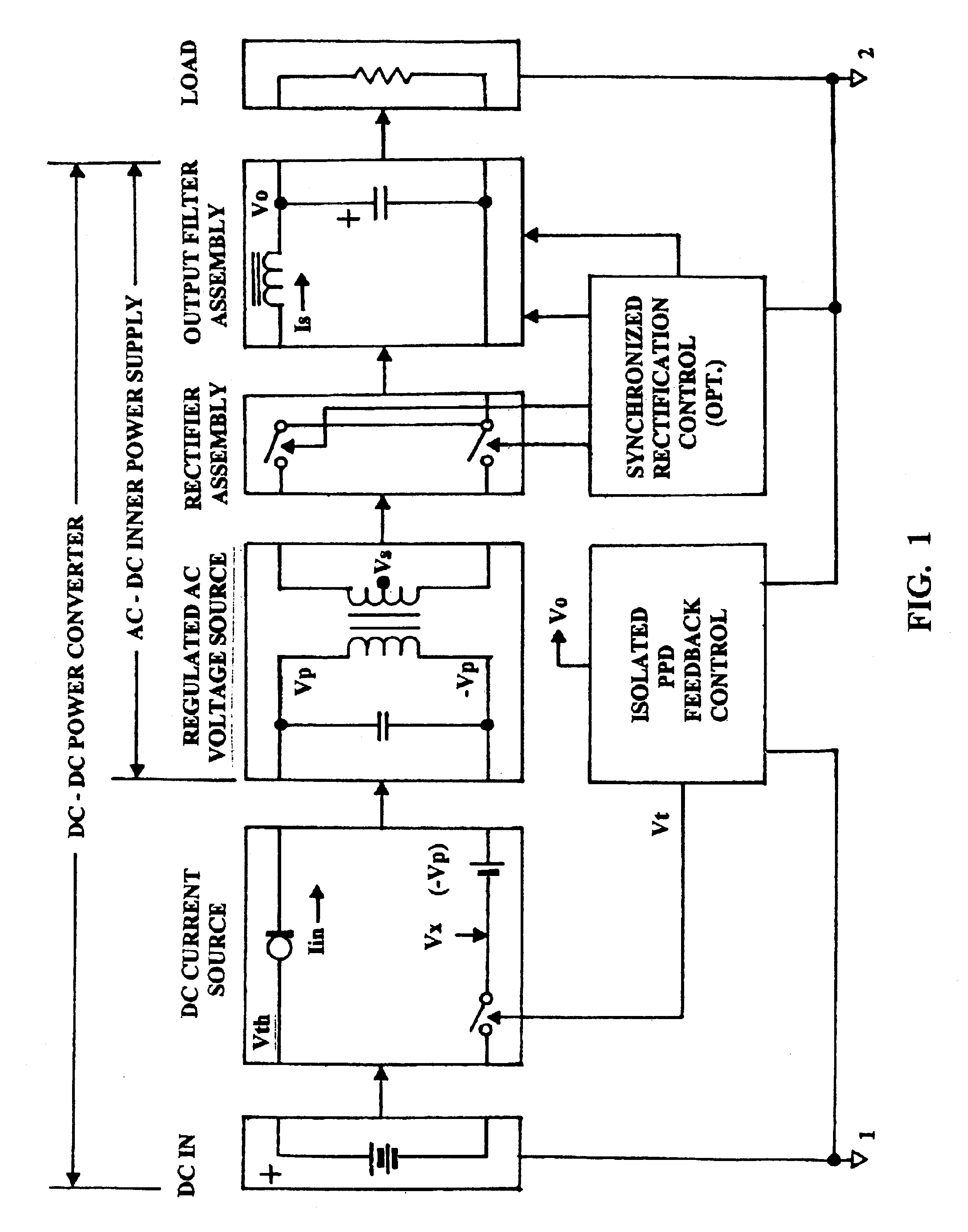
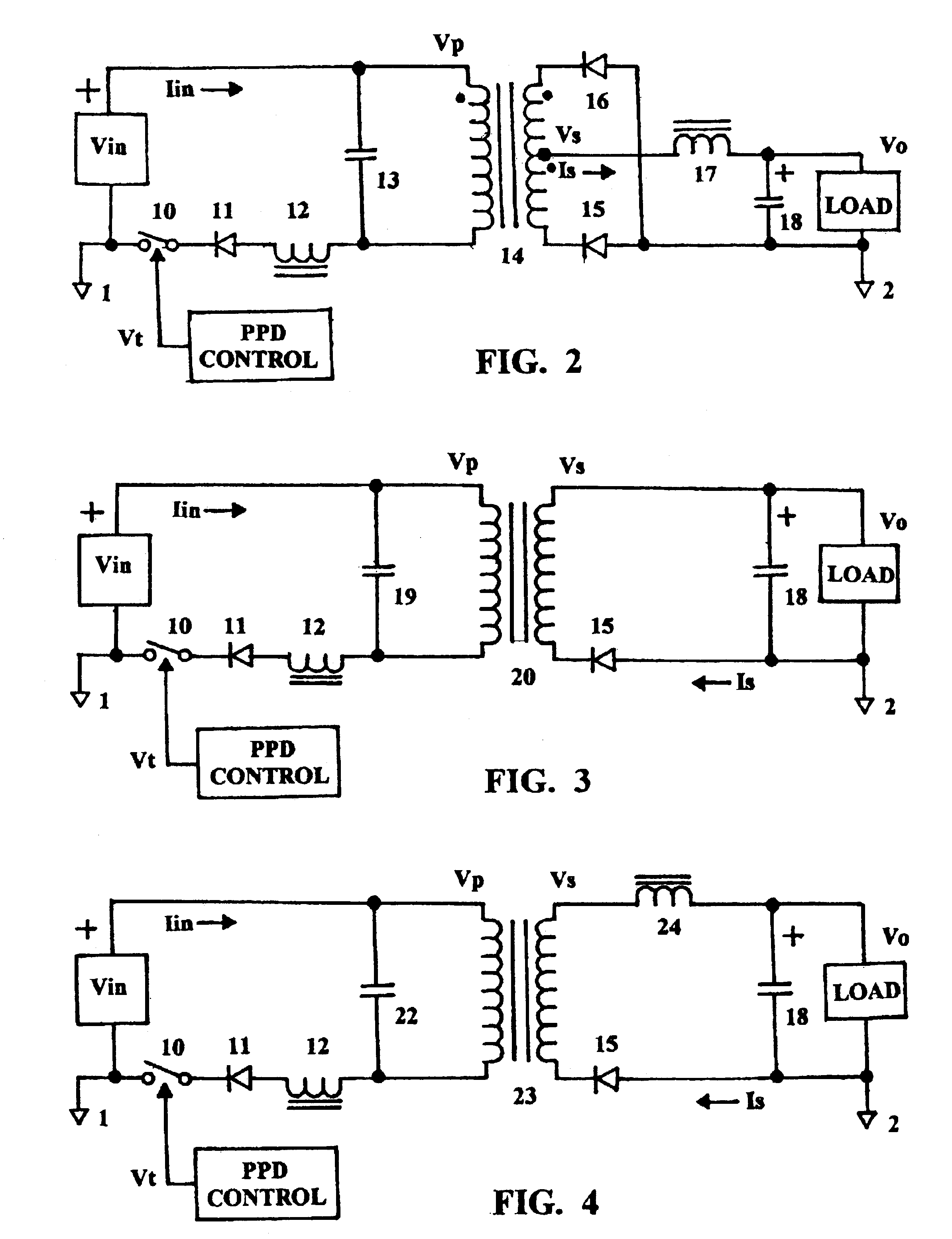
An overview of the power transfer process is provided by FIGS. 7, 7A and 7B. FIG. 7 plots the slope of Fn / Fo vs. design coefficient K. Where design coefficient K is a multiplier applied to the frequency of natural resonance, Fn, to derive an inverse function resulting in slope Fn / Fo.

FIG. 7A describes image impedance reflected from the load through a power isolation transformer to a resonant capacitor during time period of forced oscillation Fo. This impedance is defined as:

Zp=.omega.LR / (.omega..sup.2 L.sup.2 +R.sup.2).sup.1 / 2 (eq. 1)

Impedance Zp acts upon resonant capacitor Cr in a manner to create a time-constant describing the discharge rate for capacitor Cr during the time forced oscillation frequency component, Fo. Where power switch 10 has opened and transformer 14 output voltage Vs is higher than Vo by the forward voltage drop of the rectifying element(s) 15 / 16. The discharge time constant then becomes:

Td=ZpCr (eq. 2)

Component Fo encloses a non-resonant, forced oscillation, fr...


PUM


Abstract

A DC power converter enclosing a regulated AC power supply within the overall design topology. The power transfer function incorporates a process wherein a portion of the negative AC signal, generated across the input winding of a power transformer, is intercepted by a power switch transitional state. The volt-second product of the intercepted AC signal is reflected into the DC input line voltage as an additive element allowing a resonant inductor to absorb the sum of both components. Thus peak voltage transferred to a resonant capacitor is two times the sum of voltage absorbed by the resonant inductor as opposed to simply doubling the DC input line voltage. Voltage across the resonant capacitor remains constant for variations in DC input line voltage within the limits of the input voltage regulating band. This is due to an inverse relationship between the DC input line voltage and voltage yielded by the negative AC signal, at point of interception by the timing pulse. The two components combine in a subtractive manner to cancel out the variation in DC input line voltage and maintain a constant voltage to the input of the AC power supply loop. Input current supplied by the Input DC line also varies inversely proportional to the applied input DC voltage within the regulating band. Thus: negative resistance describing a constant-power load line is derived directly from the peak input current.

Description

1. Field of the InventionThis invention relates to a Current-Sourced, Anti-Resonant, CSAR Technology, DC power conversion process. And more specifically, resonant power converters using a series-resonant input stage comprised in part by power provided by the input DC voltage source in addition to a voltage component extracted from the negative voltage waveform in the anti-resonant tank circuit. And subsequently reflected back into the series-resonant tank circuit, as an additive constituent to the DC source voltage. The two voltage components combine to appear as a source voltage, to the series-resonant input stage, of a magnitude greater than that of the DC source voltage acting by itself. Consequently, the voltage developed across the resonant capacitor, sourcing voltage to the anti-resonant tank, is not confined to the usual doubling of the input DC source voltage. But, rather becomes a product of the combined voltage constituents yielding a resonant capacitor voltage several ord...

Claims


Application Information

Patent Timeline
Patent Type & Authority Patents(United States)
IPC IPC(8): H02M3/24H02M3/335
CPCH02M3/33507H02M3/33592Y02B70/1433Y02B70/1475H02M2001/0058Y02B70/1491Y02B70/10H02M1/0058
Inventor FIGUEROA, SALVADOR
Owner FIGUEROA SALVADOR
Why Eureka
Try Eureka