
Optical supervisory channel apparatus and method for measuring optical properties

a supervisory channel and optical technology, applied in the direction of optical apparatus testing, instruments, structural/machine measurement, etc., can solve the problems of over-all propagation penalty proportional to the square of bit rate, and optical signals experiencing certain nonlinear interactions. , the effect of multi-path interference (mpi) and chromatic dispersion

Inactive Publication Date: 2004-07-20
CIENA
View PDF3 Cites 66 Cited by
  • Summary
  • Abstract
  • Description
  • Claims
  • Application Information

AI Technical Summary

Problems solved by technology

Thus, the combination of increasing spectral broadening and decreasing distortion tolerance makes the overall propagation penalty proportional to the square of bit-rate.
Second, optical signals experience certain nonlinear interactions when propagating along the optical fiber.
Thus, the specific routes taken by the different WDM signals are varied which leads to variations in the link loss, multi-path interference (MPI) and chromatic dispersion experienced by the different WDM signals as they traverse diverse paths.
Besides requiring a separate instrument, this makes real-time measurements on an installed system impossible.
After the system is installed a new measurement cannot be made.
Thus, if the original measurement data is lost or inaccurate the system performance will suffer and cannot be corrected.
Further, it assumes that the system is fully functional and able to carry data which is also not true in a case of a new installation.
Another problem that is potentially damaging to fiber-optic communication systems is multi-path interference.
This problem arises where there are two or more optical reflections along the optical fiber link.
Signals arising at these reflections have a delayed arrival time at the receiver with respect to the main signal, giving rise to interferometric noise and additional performance penalties.

Method used


Image

  • Optical supervisory channel apparatus and method for measuring optical properties
  • Optical supervisory channel apparatus and method for measuring optical properties
  • Optical supervisory channel apparatus and method for measuring optical properties

Examples


Embodiment Construction

The following detailed description of the invention refers to the accompanying drawings. The same reference numbers in different drawings identify the same or similar elements. Also, the following detailed description does not limit the invention. Instead, the scope of the invention is defined by the appended claims and equivalents thereof.

The expression "optically communicates" as used herein refers to any connection, coupling, link or the like by which optical signals carried by one optical system element are imparted to the "communicating" element. Such "optically communicating" devices are not necessarily directly connected to one another and may be separated by intermediate optical components or devices. Likewise, the expressions "connection" and "operative connection" as used herein are relative terms and do not necessarily require a direct physical connection.

The term "service channel" as used herein refers to a wavelength of an optical communication system such as a WDM, SON...


PUM

PropertyMeasurementUnit
dispersion-limited propagation distancesaaaaaaaaaa
wavelengthsaaaaaaaaaa

Abstract

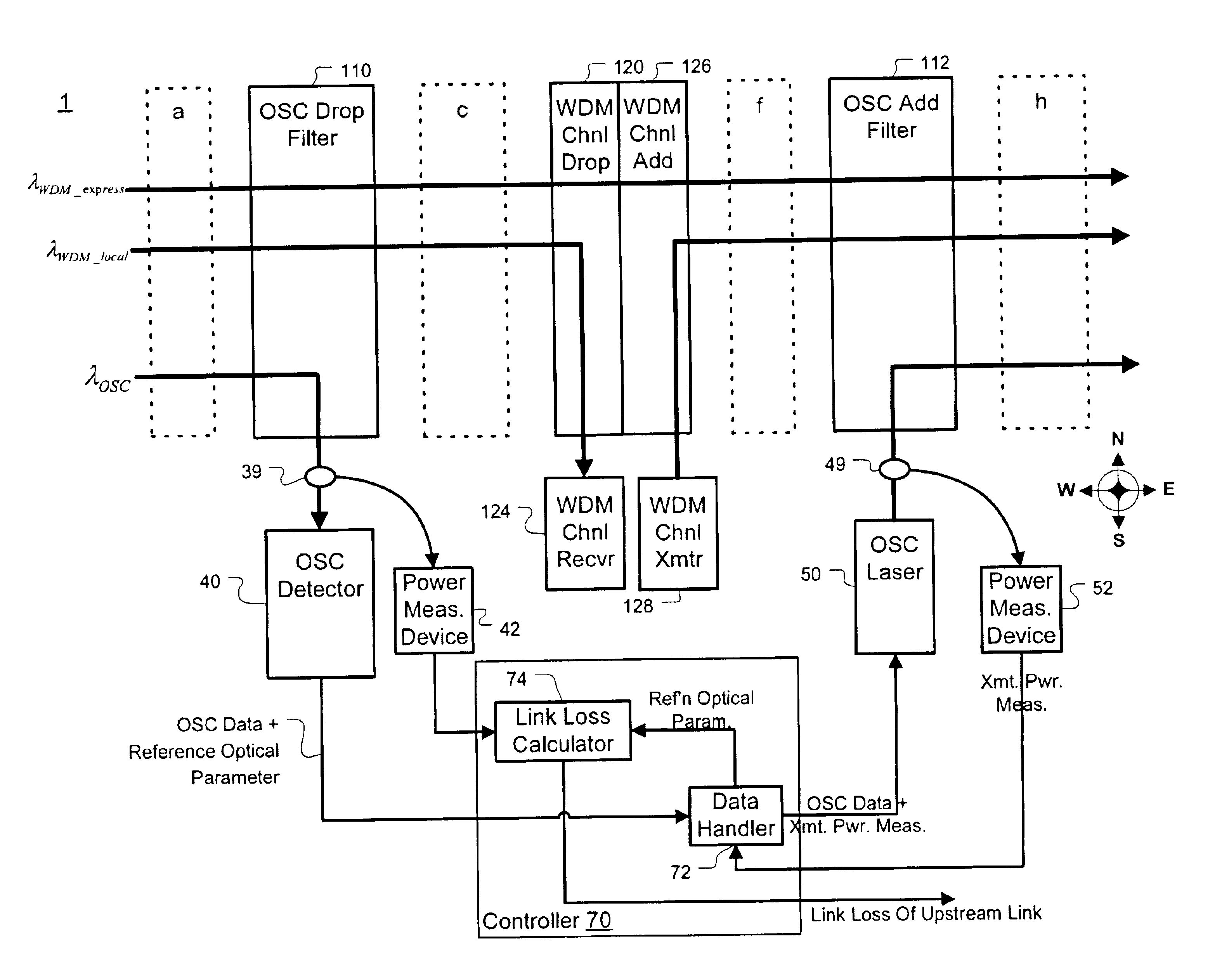
A service channel modem is adapted to determine optical properties of an optical fiber link connecting two nodes. The optical service channel (OSC) communicates an optical reference parameter over the fiber link. An optical parameter of the OSC transmitted over the fiber link is measured. By recovering the optical reference parameter from the OSC and using the measured optical parameter, certain optical properties may be determined including link loss, multi-path interference, and chromatic dispersion. When measuring chromatic dispersion, one of the fiber links serves as a synchronization reference and the other is the link being measured.

Description

1. Field of InventionThe invention generally relates to measuring, in situ, optical parameters using an optical supervisory channel. More particularly, the invention relates to adapting conventional service channel modems, or other devices handling an optical supervisory channel, to measure optical parameters such as chromatic dispersion, link loss, and multi-path interference.2. Description of Related ArtFiber-optic communication networks are experiencing rapidly increasing deployment. Especially rapid is the growth of segments that carry multi-gigabit digital data on multiple wavelengths over a single fiber strand. There are two major areas that have seen substantial increases in performance.The first area is the rapidly increasing bit-rate of a single communication channel. While several years ago 622 Mbps and 2.5 Gbps rates were dominant, current networks are being deployed with 10 GBps data rates, and new network plans using 40 Gbps data rates are being proposed. When modulated...

Claims


Application Information

Patent Timeline
Patent Type & Authority Patents(United States)
IPC IPC(8): G01N21/00G01M11/00H04B10/08
CPCG01M11/338H04B10/0775
Inventor BHATNAGAR, VIPULSRIDHAR, BALAKRISHNANFRANKEL, MICHAEL Y.DASIKA, PRASAD
Owner CIENA
Learn More