Light-receiving device and image sensor
a light-receiving device and image-detecting technology, applied in the direction of radio-controlled devices, pulse techniques, instruments, etc., can solve the problems of low sensitivity and stability of cell-use proteins, low s/n ratio of image detection under dark light sources, and high cos
- Summary
- Abstract
- Description
- Claims
- Application Information
AI Technical Summary
Benefits of technology
Problems solved by technology
Method used
Image
Examples
example 1
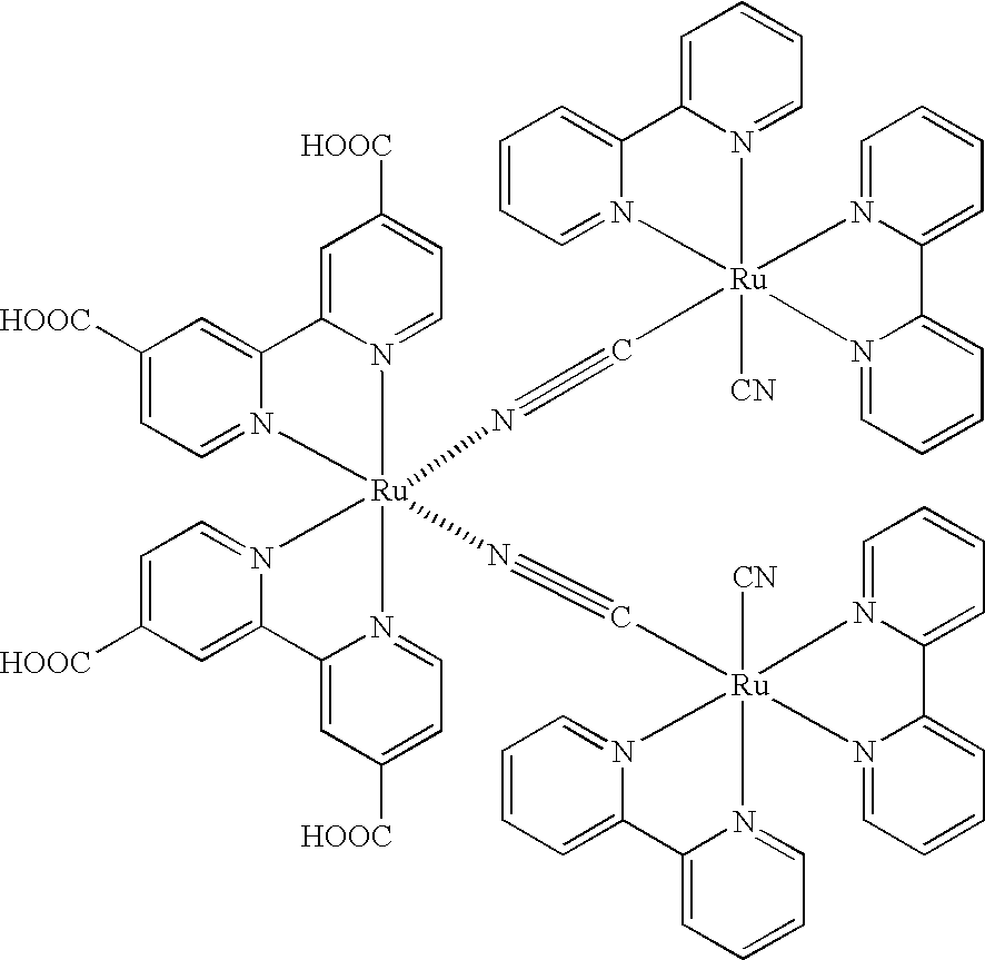
Differential Response Light-receiving Device
1-1. Preparation of Titanium Dioxide Dispersion
15 g of titanium dioxide "Degussa P-25" manufactured by Nippon Aerosil K.K., 45 g of water, 1 g of dispersant "Triton X-100" manufactured by Aldrich, and 30 g of zirconia beads having a diameter of 0.5 mm manufactured by Nikkato K.K. was charged in a stainless steel vessel coated with teflon inside having an inner volume of 200 ml, and subjected to a dispersion treatment for 2 hours at 1500 rpm by means of a sand-grinder mill manufactured by Imex K.K. After the dispersion treatment, the zirconia beads were removed by filtration to obtain a titanium dioxide dispersion. The titanium dioxide particles had an average particle diameter of 2.5 .mu.m, the particle diameter being measured by Master Sizer manufactured by MALVERN.
1-2. Preparation of Dye-sensitized TiO.sub.2 Electrode
The above titanium dioxide dispersion was applied to an electrically conductive surface of a conductive glass having a flu...
example 2
Image Sensor Using Differential Response Light-receiving Device
2-1. Preparation of Transparent Electrically Conductive Glass Substrate
Fluorine-doped, conductive fin dioxide was vapor-deposited on a surface of a non-alkali glass plate having a thickness of 1.9 mm by CVD method while using a photo-mask for patterning, to prepare a transparent electrically conductive glass substrate having a patterned, electrically conductive layer shown in FIG. 19. The electrically conductive layer was composed of: 64 square pixels 610 of 2.5 mm.times.2.5 mm in size; output terminals 620 placed in edges of the substrate; and wirings 630 having a width of 100 .mu.m connecting the pixels 610 to the output terminals 620. The electrically conductive layer had a thickness of 600 nm, a surface resistance of 10.OMEGA. / square, and a light transmittance at 500 nm of 85%. Then, the wirings of the electrically conductive layer were coated with an insulated, vapor-deposited silicon dioxide film having a thickness...
example 3
Composite Light-receiving Device
3-1. Production of Composite Light-receiving Device
As shown in FIG. 21(a), two semiconductor electrodes 700 were prepared by cutting the dye-sensitized TiO.sub.2 electrode produced in above "1-2." and by partly scraping off the dye-sensitized photosensitive layer 710. As shown in FIG. 21(b), a counter electrode 800 was prepared by heat welding spacers 500 of the heat-shrinkable resin sheet "FUSABOND" manufactured by Du Pont having a thickness of 25 .mu.m to the both faces of a glass substrate coated with ITO electrically conductive films. Incidentally, inlets were disposed on corner portions of the spacers 500.
The counter electrode 800 was sandwiched between the two semiconductor electrodes 700 and heat welded to the semiconductor electrodes 700 while applying a pressure, to prepare a cell shown in FIGS. 21(c) and 21(d). Herein, the counter electrode 800 was sandwiched between the semiconductor electrodes 700 such that the photosensitive layers 710 we...
PUM
 Abstract
Description
Claims
Application Information
 - R&D
- Intellectual Property
- Life Sciences
- Materials
- Tech Scout
- Unparalleled Data Quality
- Higher Quality Content
- 60% Fewer Hallucinations
Browse by: Latest US Patents, China's latest patents, Technical Efficacy Thesaurus, Application Domain, Technology Topic, Popular Technical Reports.
© 2025 PatSnap. All rights reserved.Legal|Privacy policy|Modern Slavery Act Transparency Statement|Sitemap|About US| Contact US: help@patsnap.com


