
Piecewise linear cost propagation for path searching

a cost propagation and path technology, applied in the field of piecewise linear cost propagation for path searching, can solve the problems of failure to find a path, long computational time, failure to achieve,

Inactive Publication Date: 2003-12-16
ORACLE INT CORP
View PDF1 Cites 63 Cited by
  • Summary
  • Abstract
  • Description
  • Claims
  • Application Information

AI Technical Summary

Benefits of technology

This approach significantly enhances computational efficiency by reducing the number of steps required for path search and routing, ensuring the finding of optimal paths even in complex scenarios, and providing a compact graph search that outperforms traditional grid graph methods.

Problems solved by technology

For any given two points inside the clear space, the minimum cost path search problem is to find the path with the minimum cost (e.g., the shortest path or by some other measure) inside the clear space that connects them.
Existing approaches to solving this problem typically suffer from at least one, and sometimes all of the following disadvantages: (i) complexity, (ii) overlong computational time, (iii) failure to achieve an optimal path when multiple paths exist, (iv) failure to find a path when one exists.

Method used


Image

  • Piecewise linear cost propagation for path searching
  • Piecewise linear cost propagation for path searching
  • Piecewise linear cost propagation for path searching

Examples


Embodiment Construction

)

The following discussion is intended to provide a detailed description of at least one example of the invention and should not be taken to be limiting of the invention itself. Rather, any number of variations may fall within the scope of the invention which is properly defined in the claims following this description.

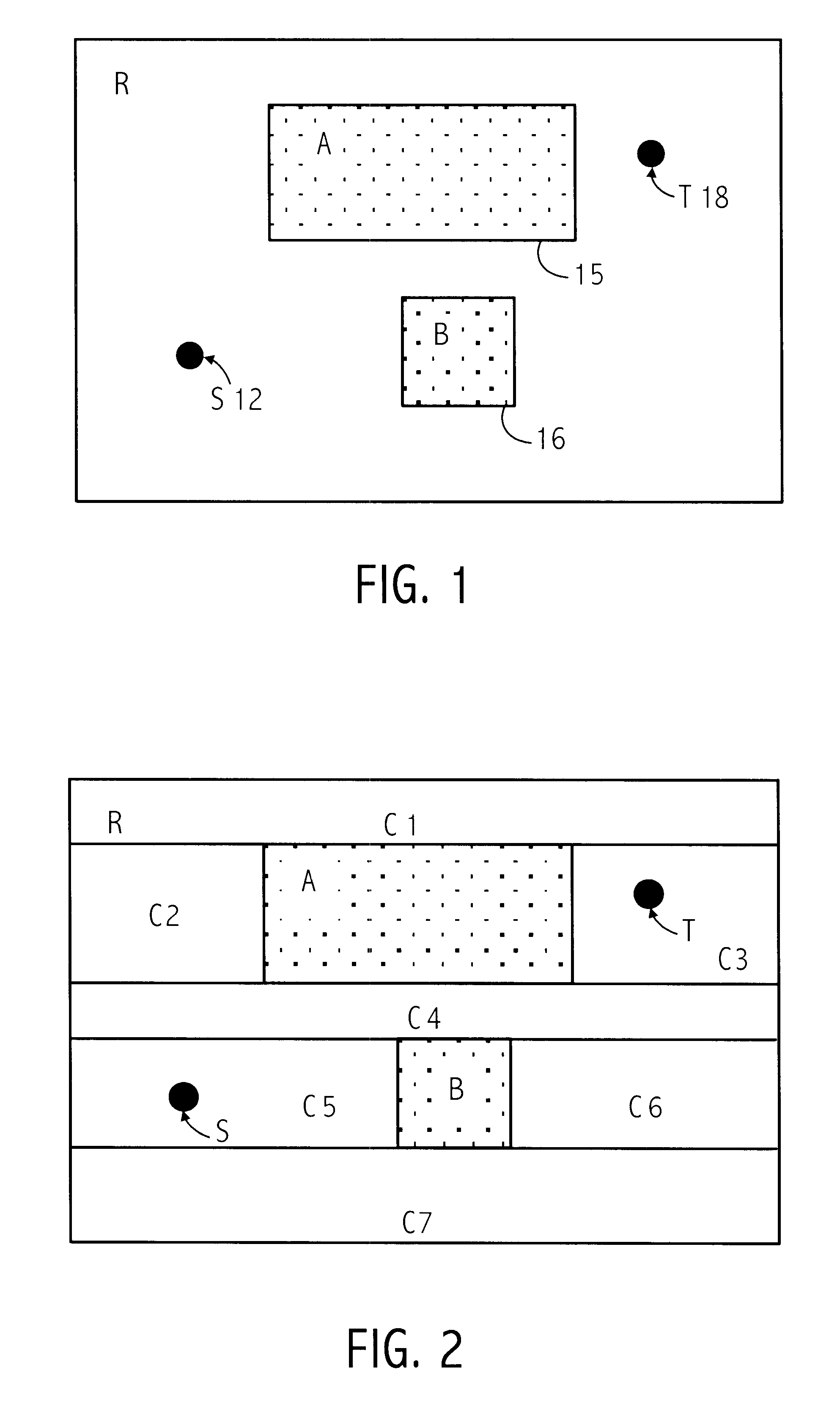
FIG. 1 shows an example of a routing area 10 including obstacles 15 and 16 (sometimes designated "A" and "B," respectively). In the embodiment shown, the goal is to find a path from source 12 (sometimes designated "S") through the clear space of routing area 10 around obstacles 15 and 16 to target 18 (sometimes designated "T"). As used herein, the source and target are locations or end points between which a path is desired and are distinguished by an arbitrary decision to start searching for the target end point starting at the source end point. Also, during much of the following discussion, the source and target are treated as points. However, it will be understood b...


PUM


Abstract

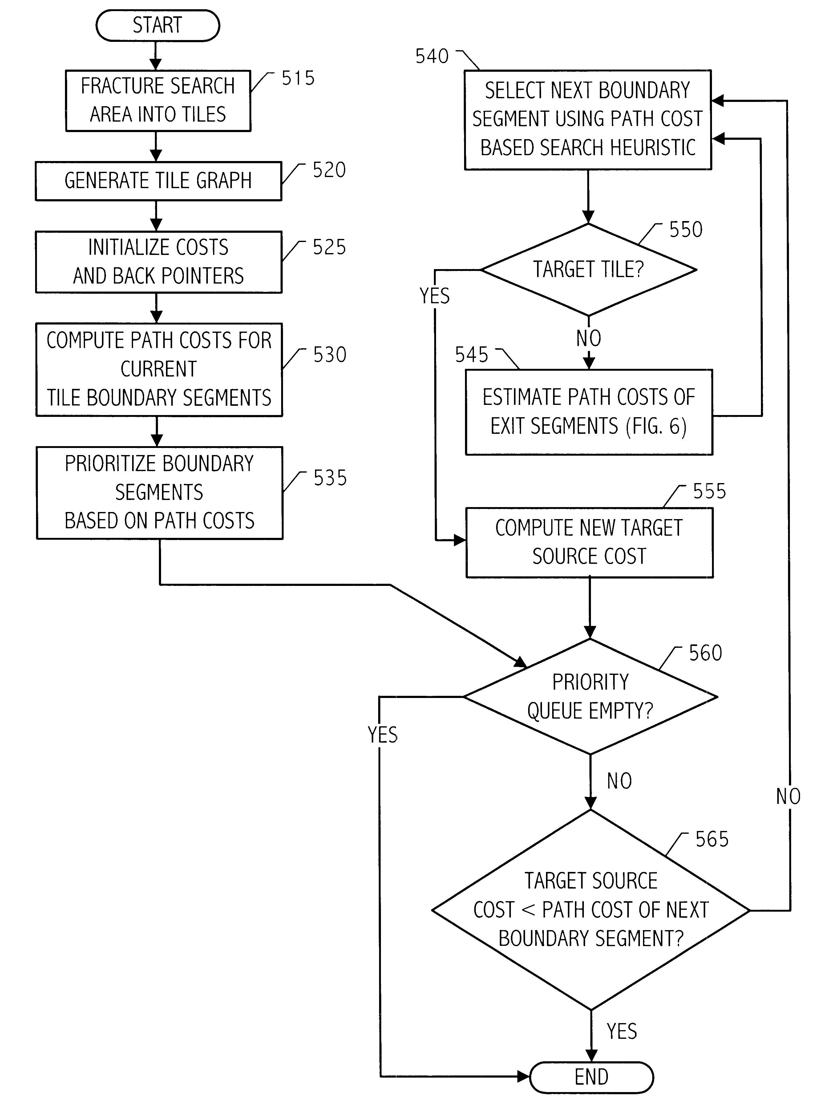
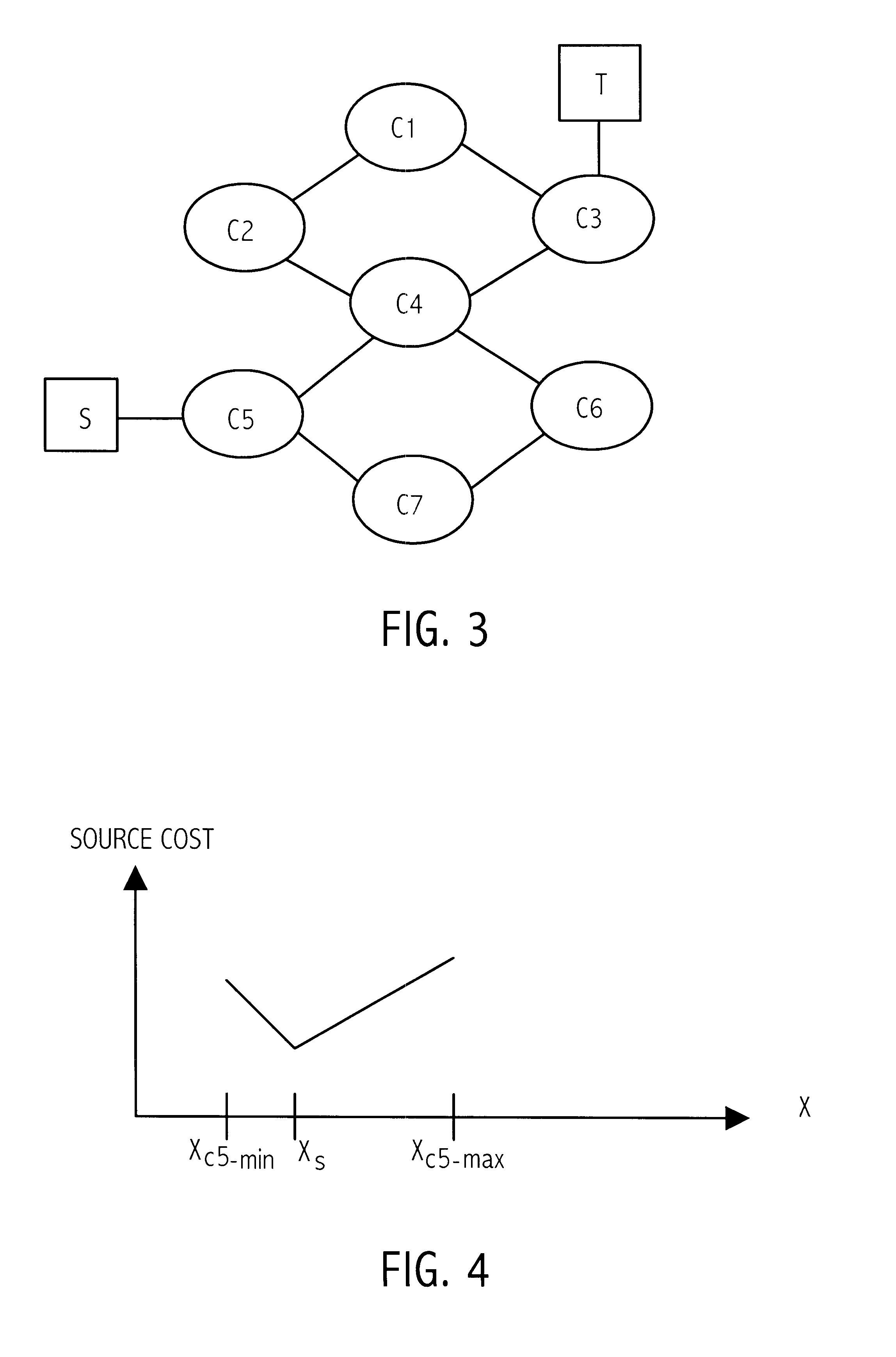
The problem of searching for a low cost path from a source location to a target location through a traversable region partitioned into a plurality of tiles is solved using source and target cost functions. Each tile in the traversable region is defined by boundary segments. The source cost function provides a cost for traversing from the source location to the boundary segment in question. The target cost function provides a cost for traversing from the boundary segment in question to the target location. The target cost function is estimated, and the source cost function is calculated. A path cost function is determined by adding the source and target cost functions. If the target location is a tile, then the target cost may be estimated using a convex hull of the target tile and the boundary segment in question. To facilitate the cost function calculations, multiple forms of cost function propagation between segments are disclosed.

Description

1. FieldThe present invention relates to path search techniques and, more particularly, to systems and methods to aid routing around obstacles such as for integrated circuit (e.g., VLSI) routing.2. Description of the Related ArtThere are many important practical applications for path searching. The classic, student's example is the traveling salesman searching for an efficient path to visit a list of locations. Some search methods are useful to plan the movement of a robot across a room around obstacles such as furniture or the movement of a robot arm through space around obstacles. One practical and currently very important engineering application of path searching is found in the semiconductor and electronics arts. Path searching and routing techniques are typically employed for layout of conductive traces. Other practical applications are well known.The classical path searching problem and current techniques can be understood in the context of searching for a shortest path from a...

Claims


Application Information

Patent Timeline
Patent Type & Authority Patents(United States)
IPC IPC(8): G06F17/50
CPCG06F17/5077G06F30/394
Inventor XING, ZHAOYUNKAO, RUSSELL
Owner ORACLE INT CORP
Learn More