
Clamp for a key duplicating machine

a duplicating machine and key technology, applied in the field of key duplicating machines, can solve the problems of escaping from the slit and falling into the moving parts of the machine, damage to the duplicating machine, and difficulty and laborious operation involved in inserting the plate into the required sli

Inactive Publication Date: 2003-11-04
SILCA SPA
View PDF9 Cites 62 Cited by
  • Summary
  • Abstract
  • Description
  • Claims
  • Application Information

AI Technical Summary

Problems solved by technology

A first drawback consists of the fact that the plate represents a removable element, which requires an actual operation for its removal once the key has been positioned and locked on the clamp.
If this element is not removed in time, its presence can damage the duplicating machine during the notching of the key.
Another drawback consists of the fact that if the plate is erroneously left in the slit during the duplication operations, it can accidentally escape from the slit and fall into moving parts of the machine (carriage, cutter, etc.) and damage them.
Another drawback is the difficulty and laboriousness of the operations involved in inserting the plate into the required slit.

Method used


Image

  • Clamp for a key duplicating machine
  • Clamp for a key duplicating machine

Examples


Embodiment Construction

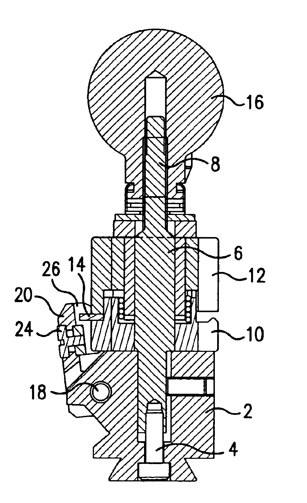
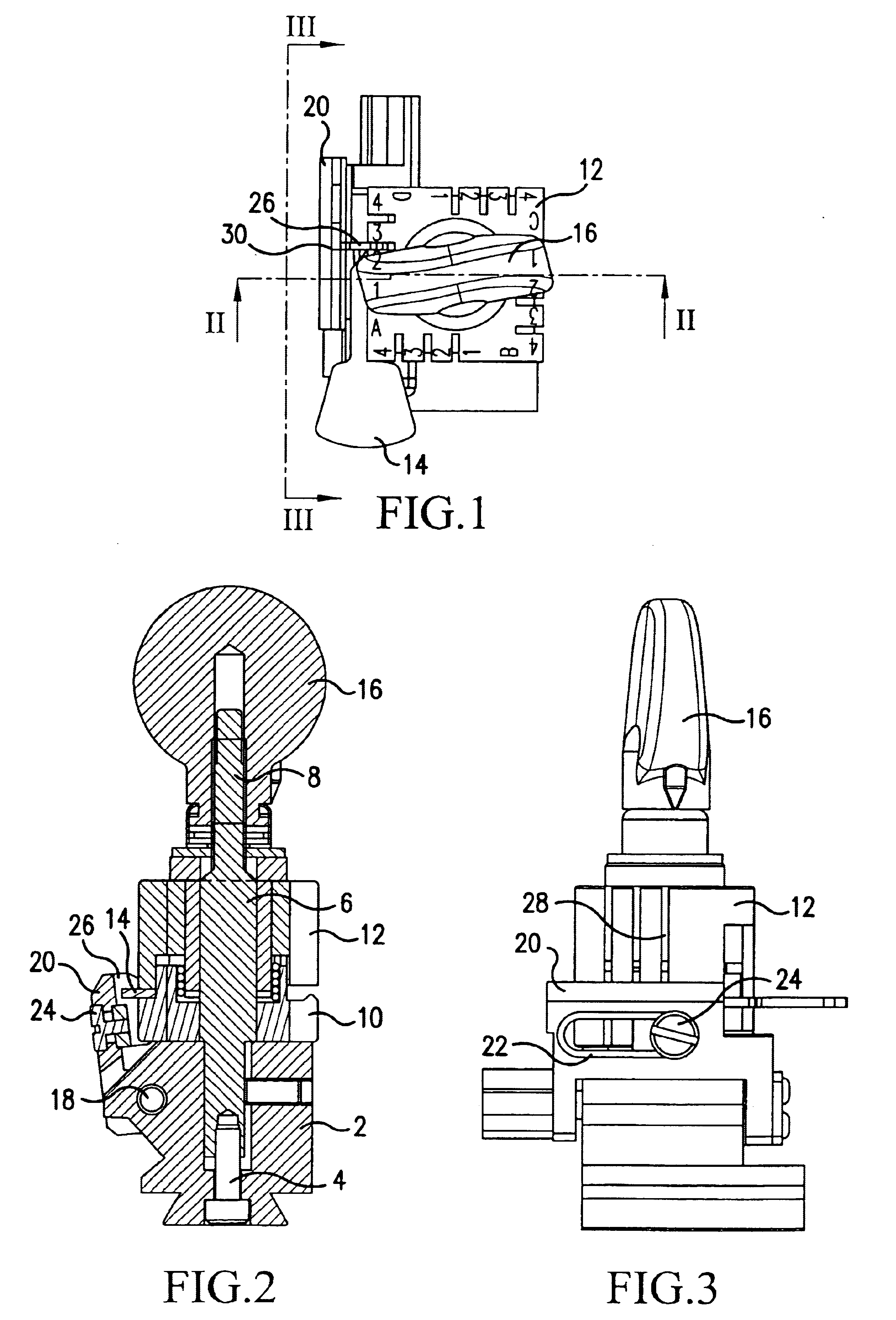
As can be seen from the figures, the clamp of the invention comprises a base 2, by which the clamp can be fixed to the structure (not shown) of the duplicating machine.

A pin 6 comprising an upper threaded portion 8 is fixed to the base 2, preferably by a screw 4.

The purpose of the pin 6 is to retain the two jaws 10 and 12 of the clamp in a perfectly superposed condition. These are square in plan view, with their facing surfaces equally or differently shaped in order to retain between them keys of different formation. More particularly, the sides of the facing surfaces of the two jaws 10 and 12 can be flat or comprise ribs complementary to any grooves present in the key 14 to be retained between the jaws.

Between the lower jaw 10 and the base 2 there can also be provided traditional means (not shown in the drawings) to ensure correct positioning of the two jaws in four different stable positions angularly rotated through 60.degree. from each other, in order to use the four sides of ea...


PUM

PropertyMeasurementUnit
timeaaaaaaaaaa
thicknessaaaaaaaaaa

Abstract

An improved clamp for key duplicating machines, comprising a pair of jaws able to approach each other and define at least one seat for clamping a key, and a gauge associable with said seat to define a correct position of said key, wherein with said gauge there is slidingly associated a counteracting element which interferes with said seat when said gauge is in its operating condition and forms a support for a tip of said key housed in said seat.

Description

The present invention relates to an improved clamp for a key duplicating machine.DESCRIPTION OF THE PRIOR ARTKnown key duplicating machines generally comprise a first clamp in which the blank key to be notched is mounted, and a second clamp in which the original key to be duplicated is mounted.The blank key and the original key must be positioned correctly in their respective clamps.This correct positioning of a key in its respective clamp is achieved by the presence (in proximity to the head of the key) of a retainer which is rested against a counteracting element or "gauge" with which the clamp is provided.For keys not provided with a retainer or in which the retainer is not reliable, the tip of the key is used as the counteracting element for its correct positioning.For this purpose each clamp is provided (in those positions in which the tip of the key could lie) with a series of slits disposed perpendicular to the seat of the key. A transverse plate, forming a support for the ti...

Claims


Application Information

Patent Timeline
Patent Type & Authority Patents(United States)
IPC IPC(8): B23C3/35B23C3/00
CPCB23C3/355Y10T409/300952Y10T409/309016
Inventor CHIES, EZIOFOSCAN, EROS
Owner SILCA SPA
Learn More