
Control for an I.S. machine

a control system and glass forming technology, applied in the direction of programme control, glass blowing apparatus, glass shaping apparatus, etc., can solve the problems of not allowing an operator to directly command the machine, not preventing the user from setting invalid or even potentially damaging sequences, etc., to achieve the effect of minimizing the wear of the displaceable mechanism

Inactive Publication Date: 2003-08-12
EMHART GLASS SA
View PDF12 Cites 12 Cited by
  • Summary
  • Abstract
  • Description
  • Claims
  • Application Information

AI Technical Summary

Benefits of technology

It is an object of the present invention to provide an improved control system for a glass forming machine which will simplify machine operation and facilitate the tuning of the machine for higher productivity.
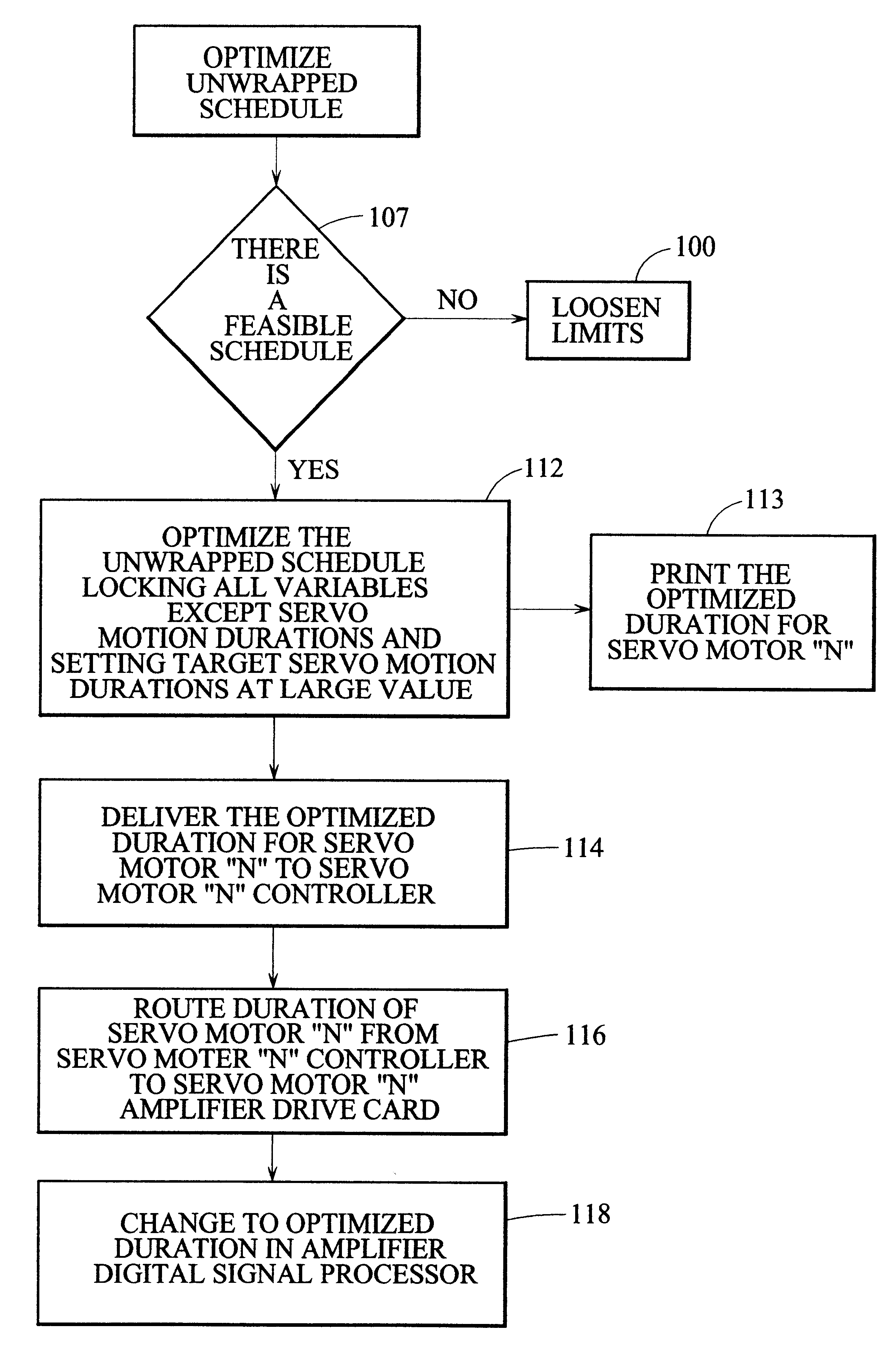
FIG. 21 is a logic diagram illustrating the operation of a control using the computerized model to minimize the wear on the displaceable mechanisms.

Problems solved by technology

This conventional approach does not allow an operator to directly command the machine to achieve desired forming durations (e.g. blank contact time, reheat time).
It also does not prevent the user from setting invalid or even potentially damaging sequences in which the mechanisms collide.

Method used


Image

  • Control for an I.S. machine
  • Control for an I.S. machine
  • Control for an I.S. machine

Examples


Embodiment Construction

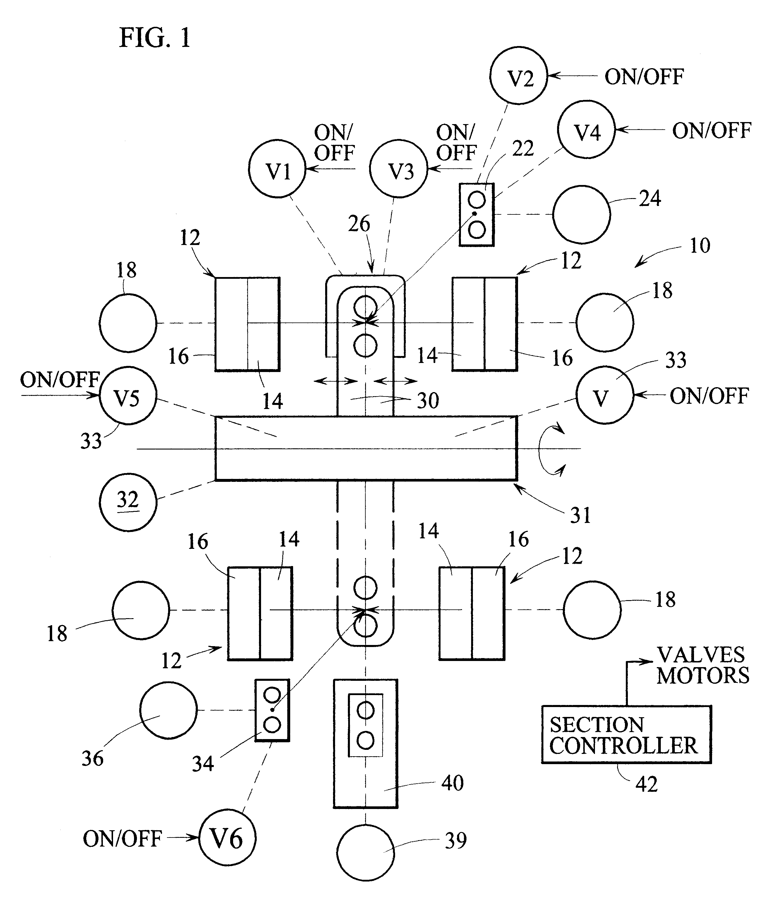
An I.S. machine includes a plurality (usually 6, 8, 10, or 12) of sections 10. Each section has a blank station including a mold opening and closing mechanism 12 having opposed mold supports 14 which carry blank mold halves. When these mold supports are closed by a suitable displacement mechanism 16 which can displace the mold support between open (illustrated) and closed positions and which is displaced by a motor 18 such as a servo motor, discrete gobs of molten glass can be delivered to the closed blank mold. The open top of the blank mold will then be closed by a baffle of a baffle support 22 which is displaceable between remote and advanced positions by a motor (such as a servo) 24. If the section is operating in the press and blow mode, the plunger of a plunger mechanism 26 is advanced vertically upwardly into the gob to form the parison. Cooling air will be supplied to the plunger via a valve V1. If the section is operating in the blow and blow mode, the finish is formed by a...


PUM

PropertyMeasurementUnit
anglesaaaaaaaaaa
event angleaaaaaaaaaa
Machine Cycle Event Anglesaaaaaaaaaa

Abstract

A control for a glass forming machine. Each machine mechanism, etc., is turned "on" and "off" at selected angles around a wrapped 360° machine cycle. The control unwraps the "on" and "off" angles around the wrapped 360° machine cycle to "on" and "off" times along an unwrapped bottle forming process which takes more than two machine cycles to complete and the unwrapped schedule is analyzed to determine whether an optimized schedule is possible and once a schedule is optimized, the analysis is done again with all the optimized values locked except one or more of the motion durations which are targeted at their maximum duration. This second optimization defines the motion durations at their longest possible setting so that the associated motor(s) can be concomitantly slowed down to minimize wear.

Description

The present invention relates to an I.S. (individual section) machine and more specifically to a control for such a machine.The first I.S. machine was patented in U.S. Pat. Nos. 1,843,159, dated Feb. 2, 1932, and 1,911,119, dated May 23, 1933. An I.S. (individual section) machine has a plurality of identical sections. Each section has a frame on which are mounted a number of section mechanisms including blank side and blow side mold open and close mechanisms, an invert and neck ring mechanism, a baffle mechanism, a blowhead mechanism, a plunger mechanism and a takeout mechanism. Associated with these mechanisms is process air used for cooling, for example. Each of the section mechanisms and the process air have to be operated at a selected time in the section cycle.In the original I.S. machine, devices (valves which operated the mechanisms and the process air, for example) had to be mechanically turned on and off each cycle and the timing process was controlled by a 360.degree. timi...

Claims


Application Information

Patent Timeline
Patent Type & Authority Patents(United States)
IPC IPC(8): C03B9/00C03B9/41G05B19/042
CPCC03B9/41G05B19/0426G05B2219/23448G05B2219/2635Y02P40/57
Inventor SIMON, JONATHAN S.
Owner EMHART GLASS SA
Learn More