
Method of operating a web-fed rotary printing machine

a rotary printing machine and web-fed technology, applied in the direction of printing, rotary letterpress machines, thin material processing, etc., can solve the problems of drive over-rated torque, drive over-loaded, and inability of the operator to set the web tension, etc., to achieve optimal tension in the web, optimal gradation of the web tension, and optimal web tension

Inactive Publication Date: 2003-06-17
MANROLANAD AG
View PDF5 Cites 12 Cited by
  • Summary
  • Abstract
  • Description
  • Claims
  • Application Information

AI Technical Summary

Benefits of technology

According to the invention, the object of maintaining desired web tension values in the folder super structure is achieved by starting up the printing machine at a selected web speed and with print thrown off from the printing unit. Web pull units are disposed in the web course downstream of the printing unit and at locations in a folder superstructure and at a folding former. These pull units each have first and second drive lead values storable in a computing and memory unit. The pull units are operated at first drive lead values to provide optimal tensions in the web. The print is then thrown on in the printing unit and the pull units are operated at the second drive lead values to provide optimal tensions in the web.
Using the method, when the printing machine is started up, even in the case of different paper grades and productions, optimal gradations of the web tension are rapidly obtained on the former and in the entire folder superstructure. As a result, even web tension problems during a production change are eliminated. The method can be automated. Overall, rejects and machine down times (web breaks) can be reduced.

Problems solved by technology

It is barely possible for the operator to set the web tension in the folder superstructure of a printing machine, for the reasons cited below.
If the adjustment facility is present, the operator is displayed only the lead, which he cannot put into order, this display often being inaccurate, for example in the case of precision adjusting mechanisms.
If the operator then makes his settings in accordance with his visual impression in such a way that there are no creases in the folder superstructure, there is no incorrect run and the pins do not tear out, the leads can be set so unfavorably that, in the case of individual electrical drives, e.g., of the pull units, some drives exceed their rated torque but others are considerably underloaded.
If the dip is too sharp, the web runs off and paper breaks occur.

Method used


Image

  • Method of operating a web-fed rotary printing machine
  • Method of operating a web-fed rotary printing machine

Examples


Embodiment Construction

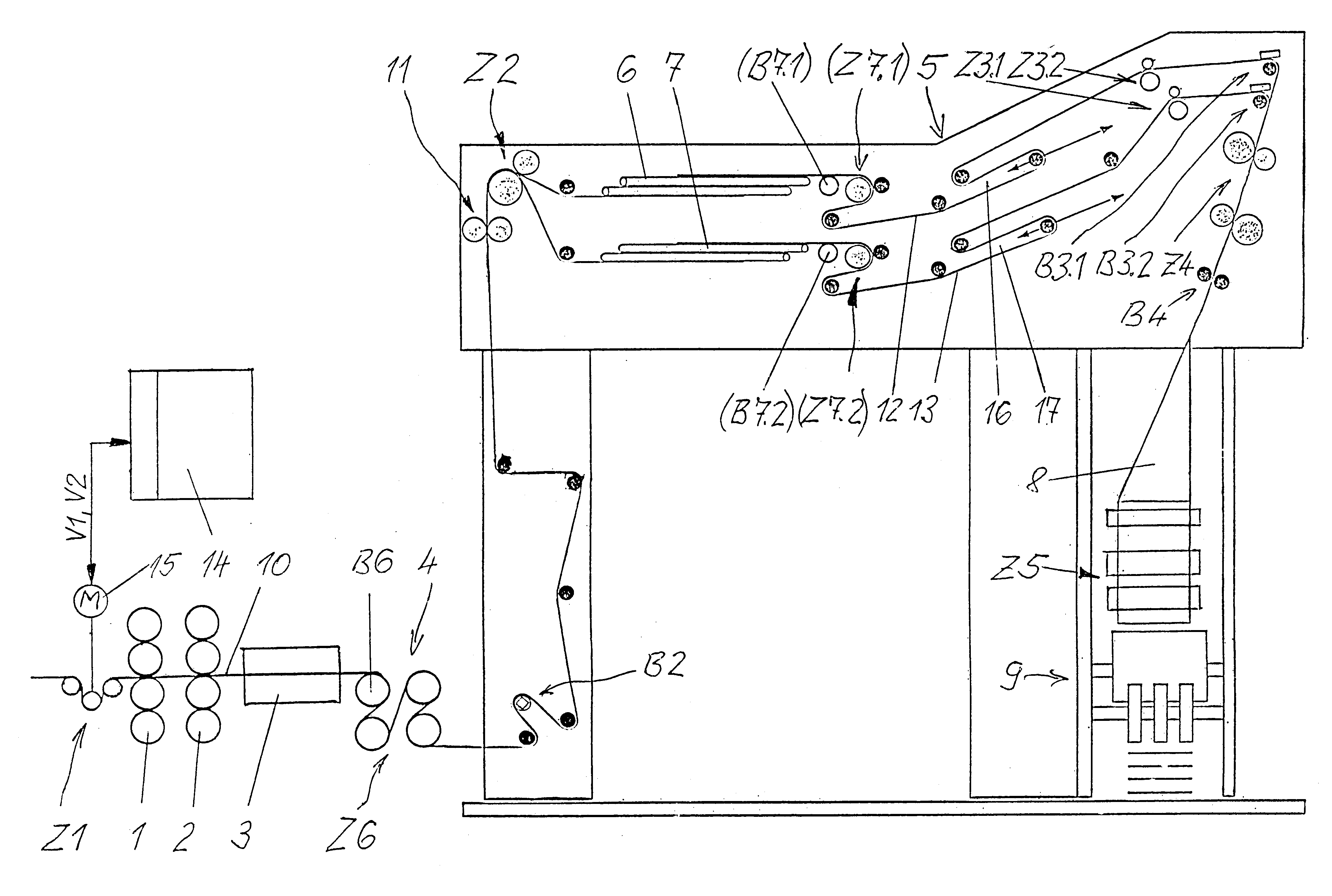
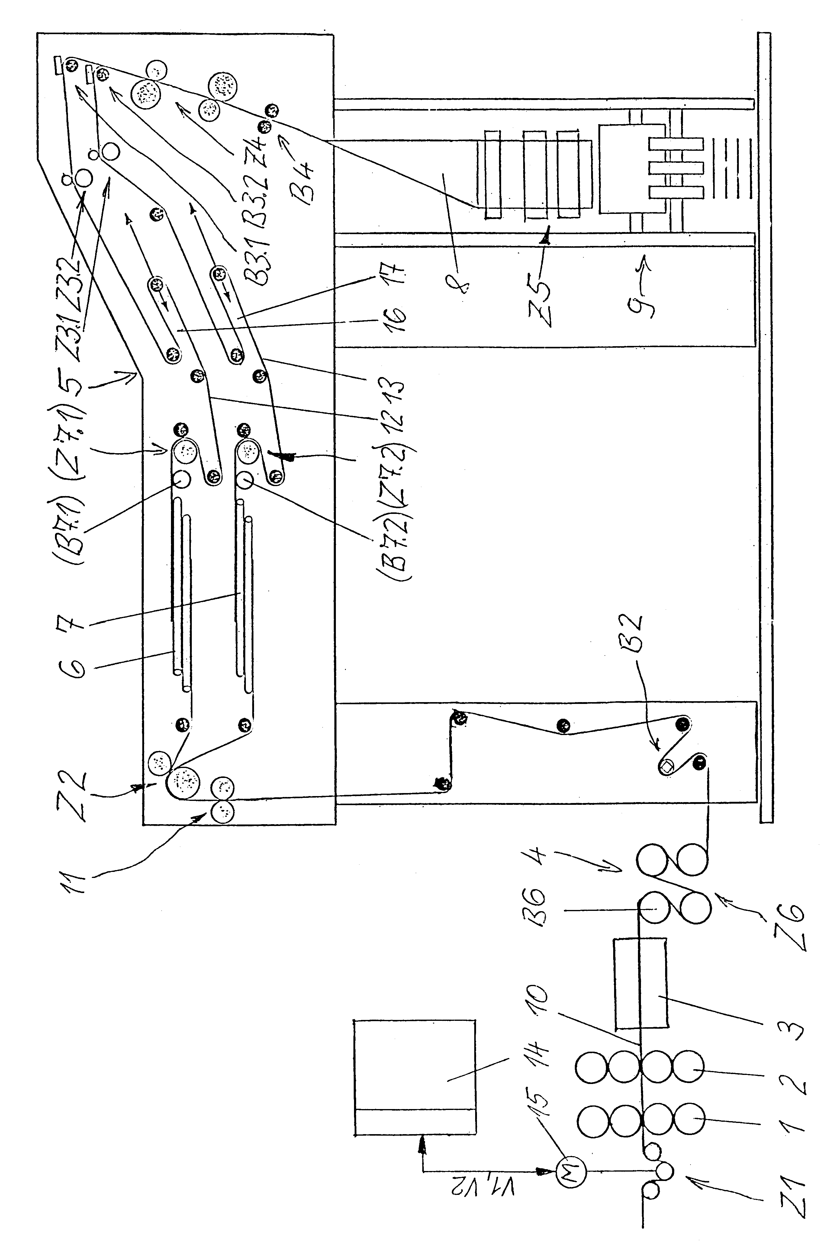
The web-fed rotary printing machine shown in the FIGURE contains a number of printing units 1, 2, a drying oven 3, a cooling unit 4, a folder superstructure 5 with turner bars 6, 7, a folding former 8 and various rolls, and a folder 9.

A web 10, on the web path through the rotary printing machine, runs successively through a first pull unit Z1 upstream of the printing unit 1, a sixth pull unit Z6 embodied by the cooling unit 4, and a second pull unit Z2 upstream of the turner bars 6, 7. A slitting device 11 divides the web 10 into two web streams 12, 13, each of which passes through one of respective third pull devices Z3.1 and Z3.2. A fourth pull device Z4 is located upstream of the folding former 8, and a fifth pull device Z5 is located downstream of the folding former 8.

The web streams 12, 13, are guided above one another by means of the turner bars 6, 7 and laid on one another before the inlet to the folding former 8. As a special case, webs which have not been slit can also be g...


PUM

PropertyMeasurementUnit
web tensionaaaaaaaaaa
speedaaaaaaaaaa
tensionsaaaaaaaaaa

Abstract

In order to reach optimal web tension relationships rapidly in the folder superstructure when starting up a web-fed rotary printing machine, first of all a web is transported with the print in the printing units thrown off, the pull units lying on the web path being operated with first lead values for optimal web tensions and, after printing has been thrown on, the pull units being operated with second lead values for optimal web tensions.

Description

1. Field of the InventionThe invention relates to a method of operating a webfed rotary printing machine, for example, a newspaper printing machine or a publication printing machine.2. Description of the Related ArtIn such a printing machine, a web is printed by at least one printing unit and a number of web streams are guided above one another by means of turner bars and laid on one another and advance to a folding former, the web in its travel course passing through pull units the lead of which can be set.It is barely possible for the operator to set the web tension in the folder superstructure of a printing machine, for the reasons cited below. Very often, adjustment facilities for the lead of pull units are not present. If the adjustment facility is present, the operator is displayed only the lead, which he cannot put into order, this display often being inaccurate, for example in the case of precision adjusting mechanisms.If the operator then makes his settings in accordance wi...

Claims


Application Information

Patent Timeline
Patent Type & Authority Patents(United States)
IPC IPC(8): B41F13/02B65H23/188B65H23/192
CPCB41F13/02B65H23/192Y10S101/42B65H2513/514B65H2701/1864B65H2301/4148B65H2513/512
Inventor SCHRAMM, MICHAEL
Owner MANROLANAD AG
Learn More