
On-location video assistance system with computer generated imagery overlay

a technology of computer generated imagery and assistance system, which is applied in the field of video playback system, can solve problems such as unconvincing, actors moving around, and problems such as blocking, and affecting the effect of the

Inactive Publication Date: 2003-05-27
MICROSOFT TECH LICENSING LLC
View PDF3 Cites 60 Cited by
  • Summary
  • Abstract
  • Description
  • Claims
  • Application Information

AI Technical Summary

Benefits of technology

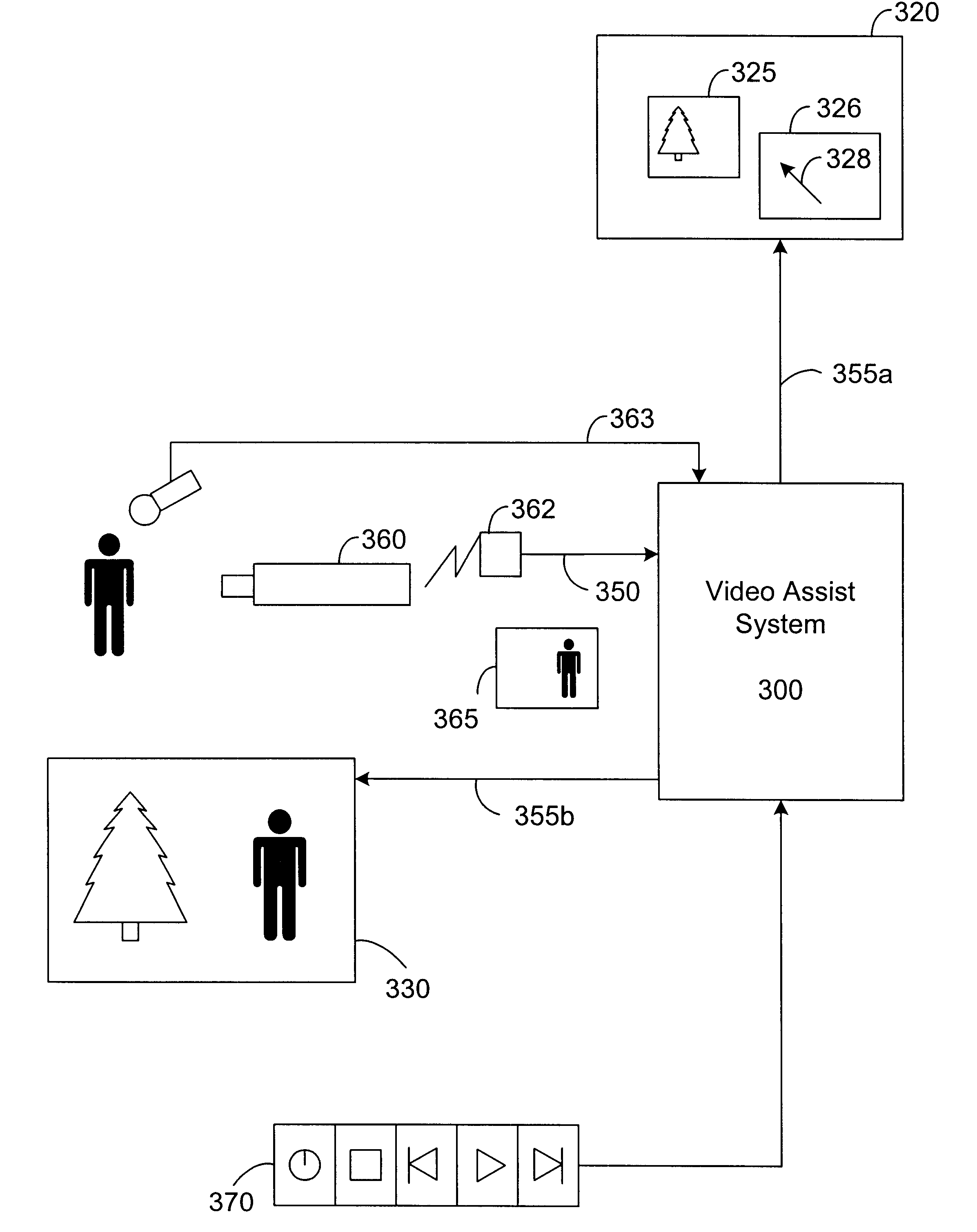
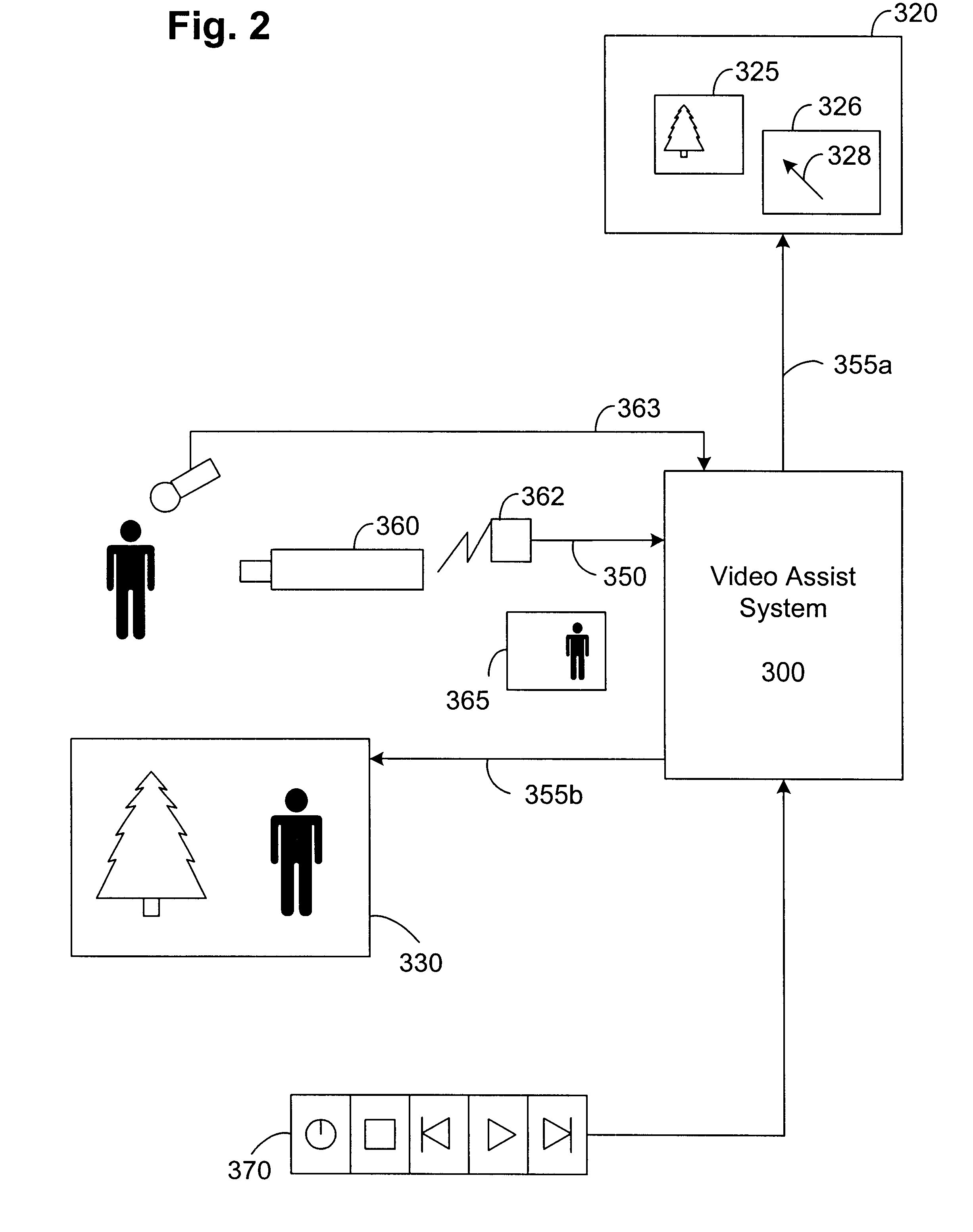
In the present embodiment, a portion of the first display screen containing computer generated imagery can be selected for overlaying on the live video feed. The video playback system of the present embodiment is also capable of storing the live video feed and the images resulted from overlaying the computer generated imagery and the live video feed. In this way, the present invention provides the advantages of allowing live / CGI (computer generated imagery) composites to be played and viewed in real-time on the director's monitor for review while on location. The video playback system of the present embodiment may also include audio inputs for receiving a live audio feed and storage for recording the audio synchronously with the live video feed. The video playback system of the present embodiment may also include a hand-held control unit for receiving control signals from a user.

Problems solved by technology

While the computer generated images and the actors may sometimes fit seamlessly together, the results are oftentimes unconvincing.
Problems may also arise when actors move around and become blocked by the CGI.
Re-shooting of a scene and extended post-production work are time consuming and are extremely expensive, and may cause significant delays in the production of a film.

Method used


Image

  • On-location video assistance system with computer generated imagery overlay
  • On-location video assistance system with computer generated imagery overlay
  • On-location video assistance system with computer generated imagery overlay

Examples


Embodiment Construction

FIG. 2 is a block diagram illustrating an on-location video assist system 300 in accordance with an embodiment of the present invention. As illustrated, video assist system 300 may be implemented with a computer system (e.g., system 101) having two video output ports 355a and 355b (e.g., video output ports 120) and a video signal input port 350 (e.g., communication device 118). In the present embodiment, video signal input port 350 is for receiving NTSC, Composite or SVHS signals transmitted from a camera 360. Also illustrated in FIG. 2 is a radio-frequency (RF) receiver 362 coupled to the input port 350 for receiving RF signals representative of video signals from the camera 360.

The first video output port 355a of the present embodiment is for coupling to a display known as an animator's monitor 320. According to the present embodiment, a user can create computer generated imagery (CGI) using animation software programs running on the computer system 101. Software programs for crea...


PUM


Abstract

A video playback system for assisting on-location film production. One embodiment of the invention includes a computer system capable of generating computer generated imagery (CGI) and receiving live video feed from a camera. The computer system is also coupled to a first display screen for displaying computer generated images and a second display screen for displaying the live video feed overlaid with computer generated images. In one embodiment of the present invention, a portion of the first display screen containing computer generated images can be selected for overlaying on the live video feed. The video playback system of the present invention is also capable of storing the live video feed and the images resulted from overlaying the computer generated images and the live video feed. The present invention provides the advantages of allowing live / CGI composites to be played and viewed on the director's monitor for review while on-location.

Description

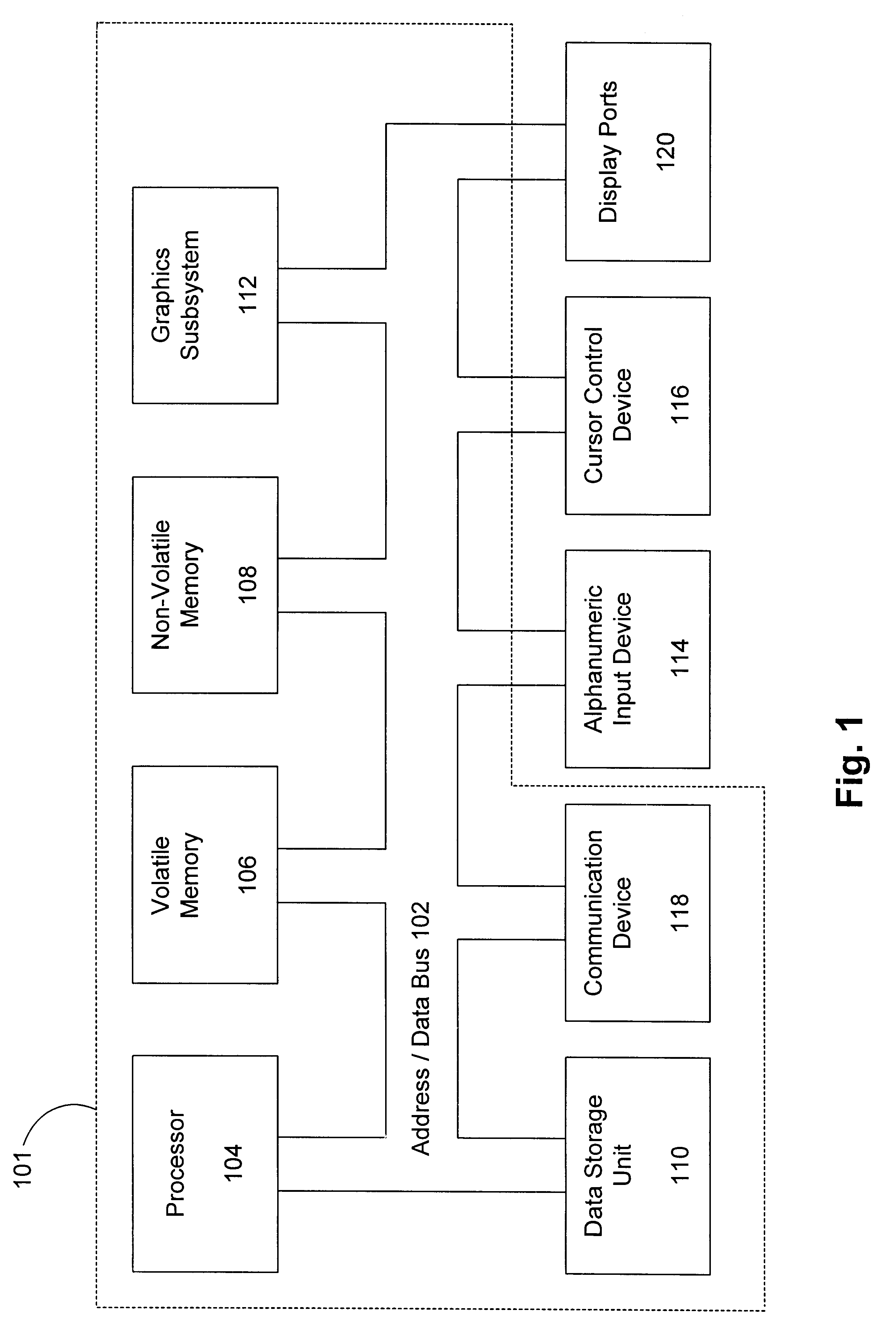
The present invention pertains to the field of film and video production. More particularly, the present invention pertains to on-location film and video production equipment.Computer graphics is used in a wide variety of applications, such as in business, science, animation, simulation, computer-aided design, process control, electronic publishing, gaming, medical diagnosis, etc. In an effort to portray a more realistic real-world representation, three dimensional objects are transformed into models having the illusion of depth for display onto a two-dimensional computer screen. This is accomplished by using a number of polygons to represent a three-dimensional object. Next, a scan conversion process is used to determine which pixels of a computer display fall within each of the specified polygons. Thereupon, texture is selectively applied to those pixels residing within specified polygons. Finally, lighting, shading, shadowing, translucency, and blending effects are applied.As thr...

Claims


Application Information

Patent Timeline
IPC IPC(8): H04N5/222G09G5/377
CPCG06T19/006H04N5/2228H04N5/2224H04N5/222
Inventor SMITH, KEVIN ANTHONY
Owner MICROSOFT TECH LICENSING LLC
Learn More