Probe type shape measuring sensor, and NC processing equipment and shape measuring method using the sensor

Inactive Publication Date: 2003-04-01
RIKEN
View PDF14 Cites 40 Cited by
  • Summary
  • Abstract
  • Description
  • Claims
  • Application Information

AI Technical Summary

Problems solved by technology

However, because the system uses analog signals, large drifts in the output occur and the detected output is not very linear, so sub-micron accuracy such as about 0.1 .mu.m cannot possibly be obtained if the overall distance moved by the sensor is about 100 .mu.m.
Consequently, the measurement pressure fluctuates as the probe moves, and a large pressure is needed for the measurement and the pressure cannot be controlled freely, and this is a practical problem.
More explicitly, a spring applies a minimum pressure of about 10 grams which is too large to obtain a high accuracy, and because the spring force varies depending on the displacement of the probe resulting in variations in the pressure, there are large measurement errors, which is also another problem.
There is another problem that if the air pressure is reduced, the stiffness of the air slide is also reduced, allowing the probe to tilt excessively, and the measurement errors are increased.
Therefore, even with a digital system, a sub-micron accuracy of about 0.1 .mu.m cannot be achieved.
However, with the device shown in FIG. 1, many optical elements such as moving mirrors and prisms are required, so the device itself becomes very large and delicate, therefore the device has the problem that it cannot be installed on a processing machine for making measurements on the machine.
However, according to this means, the times required to move the probe to the defined positions and the waiting times during which the probe is stopped accumulate, a long time is required.
In addtion as intermediate points between points cannot be measured, a large number of defined points are required, so causing the problem that very long time is required to complete the measurements.
If the driving force in the direction of the workpiece exceeds about 500 mgf, friction between the probe and the workpiece increases, resulting in a large tilt of the probe shaft, so a sub-micron accuracy of about 0.1 .mu.m cannot be obtained.

Method used


Image

  • Probe type shape measuring sensor, and NC processing equipment and shape measuring method using the sensor
  • Probe type shape measuring sensor, and NC processing equipment and shape measuring method using the sensor
  • Probe type shape measuring sensor, and NC processing equipment and shape measuring method using the sensor

Examples


embodiments

The following paragraphs describe the embodiments and analysis results of the aforementioned probe type shape measuring sensor, and the NC processing equipment and the shape measuring method using the sensor.

1. Analysis of Slipping and Tilting Errors of the Measurement Probe When Measuring a Slope

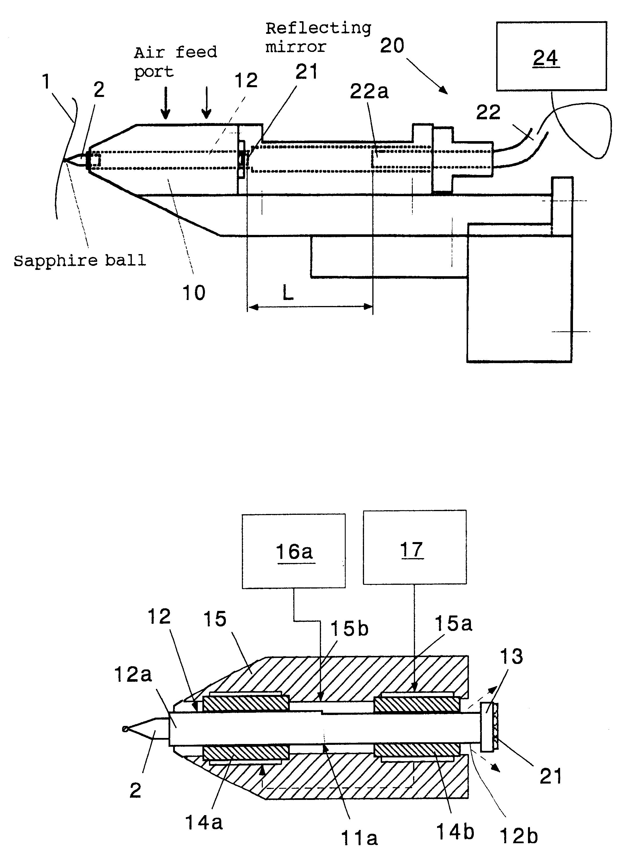
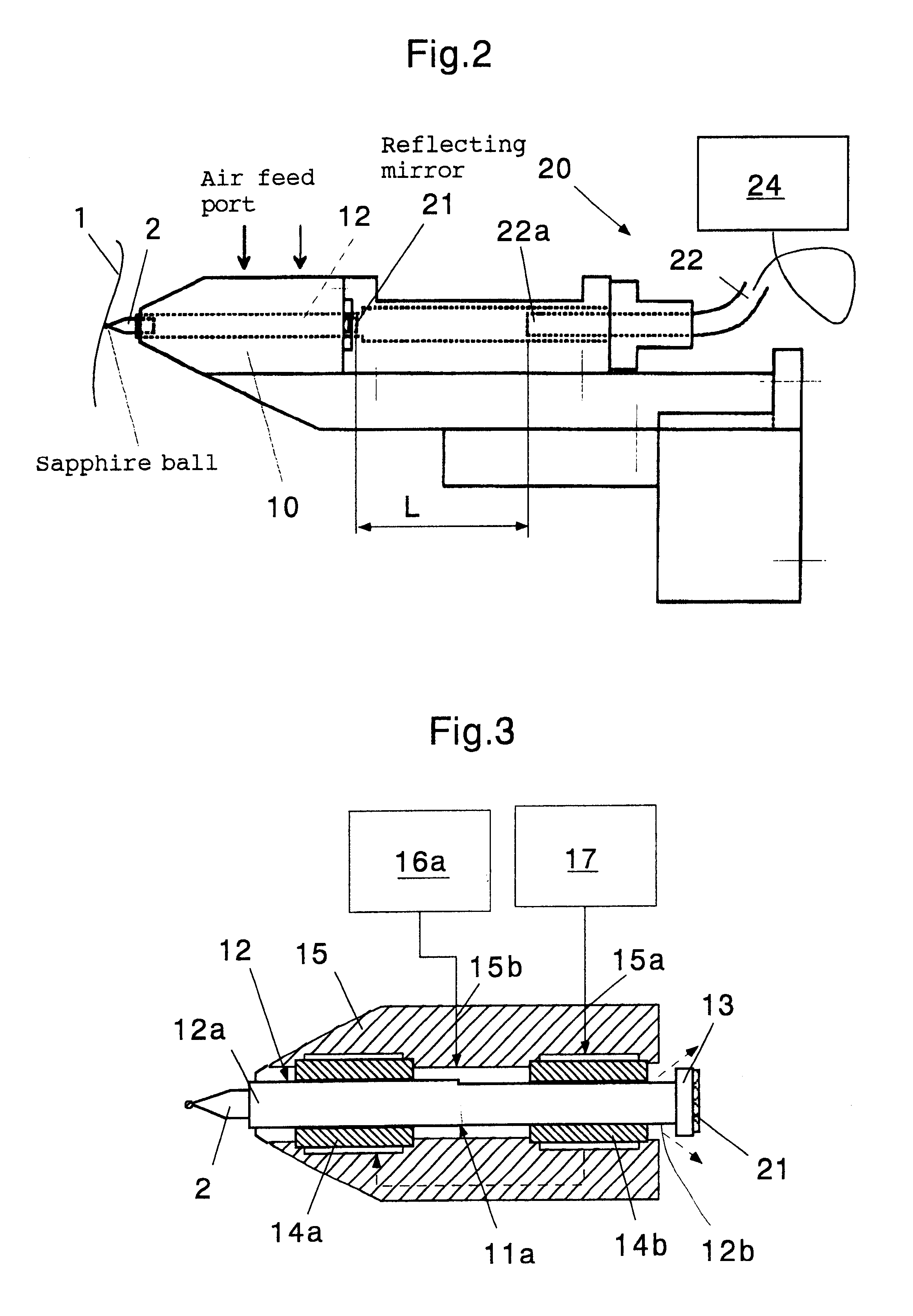
The above-mentioned FIG. 2 shows a general view of the newly developed shape measuring sensor. A sapphire ball is installed at the tip of the measuring probe, and the probe shaft 12 is supported by air slides (air bearings 14a, 14b). The reflecting mirror 21 is mounted on the opposite end of the probe shaft, and the optical fiber laser interferometric displacement meter (displacement measuring device 20) measures the displacement of the probe, thereby the shape of a workpiece can be measured in principle. The measuring pressure can be varied within a range of about 0 mgf to 500 mgf by controlling the air pressure using an electro-pneumatic regulator.

FIG. 6 shows the characteristics of the n...


PUM


Abstract

A probe head 10 and a laser interferometric displacement meter 20 are provided. The probe head supports a probe 2 that is capable of contacting a workpiece 1, that is free to move in the direction of the workpiece, and drives the probe towards the workpiece. The displacement meter measures the displacement of the probe with a high accuracy without contact. The probe head 10 is also provided with a probe shaft 12 with steps 11a, 11b at intermediate portions thereof and air bearings 14a, 14b that support the probe shaft on each side of the steps. The air bearings have a high stiffness in the radial direction, and the probe shaft is made to float by using compressed air, thus the resistance of the shaft to sliding is reduced. In addition, another compressed air is supplied to the location of the step and produces a driving force in the direction of the workpiece due to the difference of cross sectional areas on each side of the step, that provides a very small load within a predetermined range. Thereby, the measuring pressure can be adjusted to a constant very small load without reducing the stiffness of the bearings of the probe, and the measuring pressures can be varied freely. Therefore, a sub-micron accuracy of about 0.1 mum can be obtained, and the equipment can be made compact and is easily applied to on-machine measurements.

Description

1. Technical Field of the InventionThe present invention relates to a probe type shape measuring sensor, and a NC processing equipment and a shape measuring method using the sensor.2. Prior ArtWhen a workpiece must be manufactured precisely it is essential to have a technology for measuring the shape of the workpiece on the processing machine, i.e. so-called on-machine measurement technology. Such an on-machine measurement technology can improve the accuracy of the processing by eliminating the positioning errors which occur when the workpiece is removed and replaced, and at the same time the processing efficiency can be improved and the measurements can be automated and the manpower required for preparations can be saved.Apparatus for measuring the shape of a workpiece, known in the prior art, include a probe type shape measuring sensor wherein the tip of a measurement probe touches the surface of the workpiece and measures the shape thereof. Such probe type shape measuring sensors...

Claims


Application Information

Patent Timeline
IPC IPC(8): G01B11/24G01B11/00G01B21/20
CPCG01B11/007G01B21/20G01B11/2441
Inventor MORIYASU, SEIYAMAGATA, YUTAKAOHMORI, HITOSHIMORITA, SHINYA
Owner RIKEN
Why Eureka
Try Eureka