
Ink jet recovery system having variable recovery

a recovery system and variable recovery technology, applied in printing and other directions, can solve the problems of low discharge efficiency of ink or reducing the responsibility of ink discharge to the recording signal, discharge failure including ink non-discharge, and discharge failure of ink

Inactive Publication Date: 2003-03-25
CANON KK
View PDF12 Cites 12 Cited by
  • Summary
  • Abstract
  • Description
  • Claims
  • Application Information

AI Technical Summary

Benefits of technology

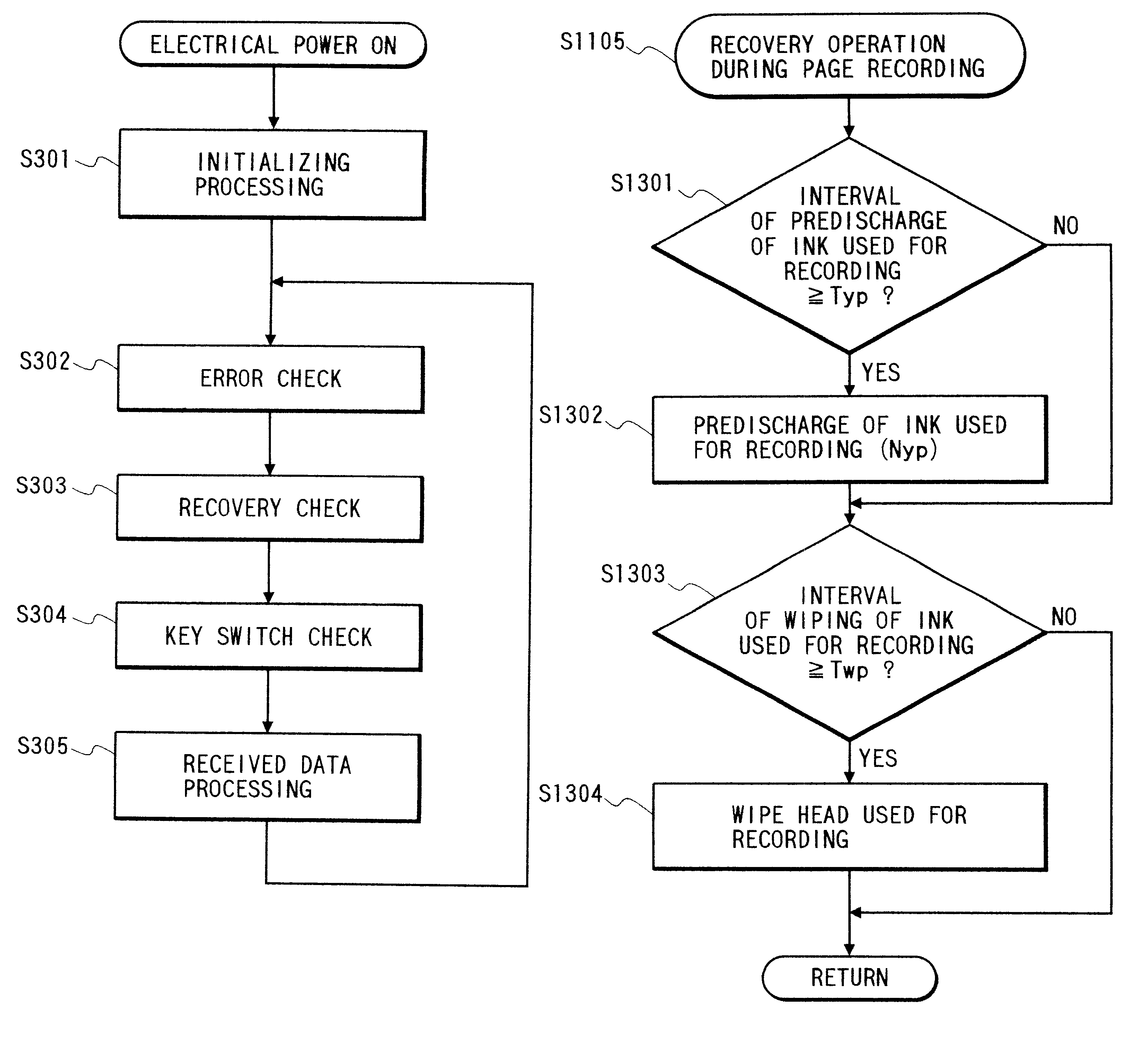
An ink jet recording apparatus of the present invention with a recording method thereof to resolve the aforementioned problems comprises discriminating means for discriminating the ink involved in the recording, an ink cartridge, or a recording head, and control means for providing recovery operation for the prevention or recovery of non-discharge of the ink from the discharge ports for discharging the ink, based on the result of said discriminating means, characterized by providing control such that the ink consumption of the recovery operation for the ink, the ink cartridge or the recording head involved in the recording is lower than that of the recovery operation for the ink, the ink cartridge or the recording head not involved in the recording. Thereby, it is possible to prevent unnecessary recovery operation or wasteful ink consumption, and effect the excellent recording.

Problems solved by technology

Since the discharge ports provided on the ink jet recording head or liquid channels in communication thereto are as small as about tens microns in inner diameter, the foreign matter such as dust or bubble, if reaching to any liquid channels, will adhere to the inner walls of liquid channels to impede the flow of ink, resulting in lower discharge efficiency of ink or reduced ink discharge responsibility to the recording signal, and in some extreme cases, clogging in discharge ports which may cause a discharge failure including ink non-discharge.
Also, when the ink is not discharged for a long time while the ink remains filled in the liquid channels of the ink jet recording head, the ink constituents will be thickened, and fixed therein, resulting in a discharge failure of the ink.
Also, in the ink jet recording apparatus, if the foreign matter such as ink droplet, water droplet or dust is attached on the ink discharge port face of the ink jet recording head, the ink droplet to be discharged may be pulled by such adhering matter, resulting in deflected discharge direction or degraded image quality.
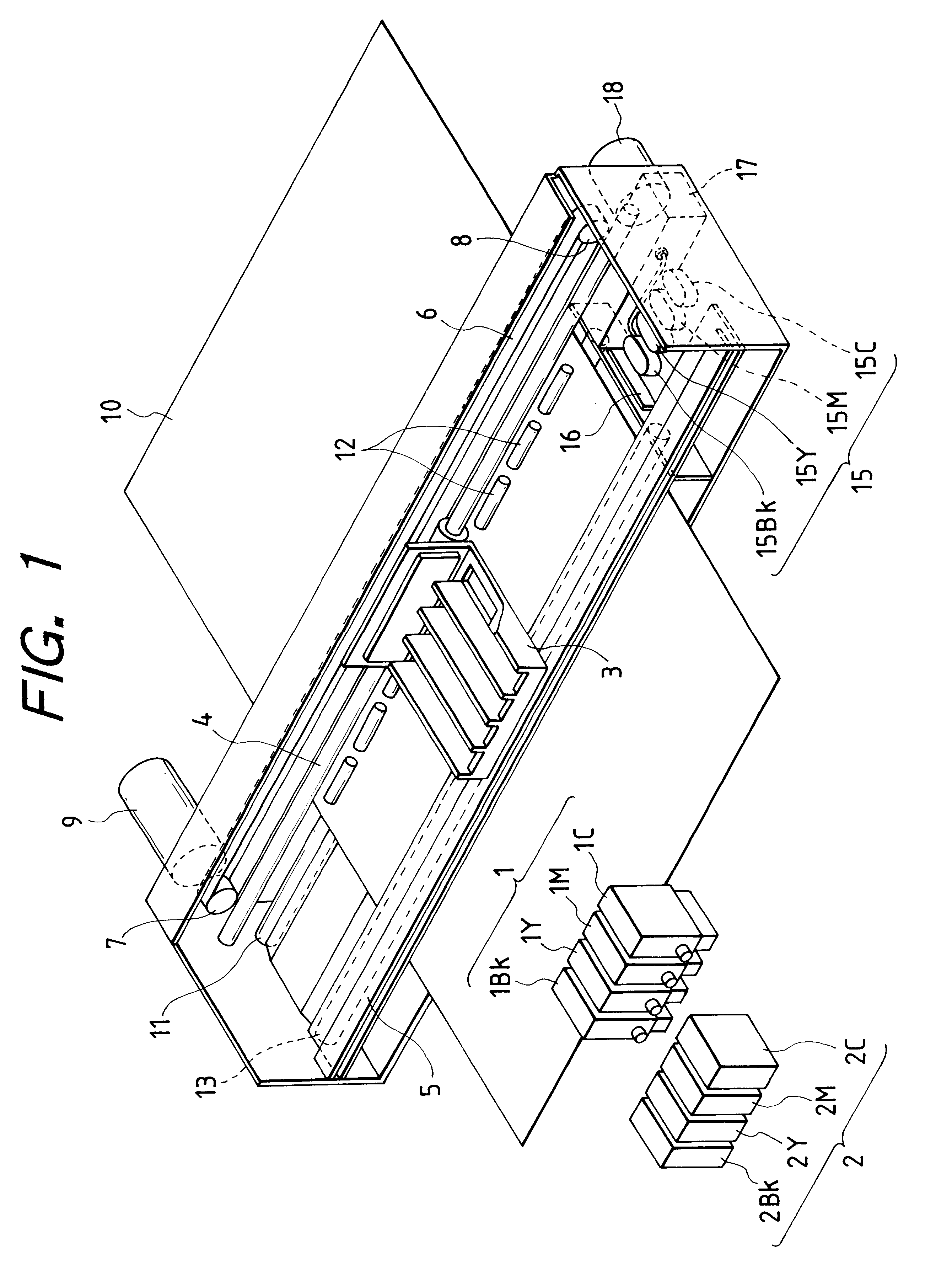
However, the ink jet recording apparatus had a problem that when a plurality of carriages with recording heads mounted thereon are provided as in the above conventional example, a plurality of recovery systems corresponding to the carriages are required, resulting in increased costs, and the lower recording speed for the switching operation of the carriages.
Furthermore, when the recovery operation is performed, based on the result of detection of the discharge, or in accordance with the history following the previous recovery operation, the predischarge and wiping during the recording are effected for all the discharge ports of the recording heads, resulting in a problem of having increased ink consumption for the recovery operation of discharging the ink not involved in the recording.

Method used


Image

  • Ink jet recovery system having variable recovery
  • Ink jet recovery system having variable recovery
  • Ink jet recovery system having variable recovery

Examples


second example

FIGS. 17, 18 and 19 illustrate the constitution of a recording head and an ink cartridge according to another example of the present invention.

FIG. 17 exemplifies one constitution in which a recording head 1701 is commonly employed for BK, Y, M and C inks, with discharge port columns 101BK, 101Y, 101M and 101C separately provided. The ink cartridges 1702BK, 1702Y, 1702M and 1702C can be exchanged independently of one another. By having the recording head 1701 integrally formed in this way, the recording head can be manufactured inexpensively. Also, where a cap member is commonly provided for all the ink discharge ports in the recording head 1701, the suction of the ink can not be made independently of other inks. Also, the wiping of the ink can not be made independently. However, the use of the recovery process of the present invention makes it possible to effect the excellent recording, with good preservation when out of service, without consuming wastefully the ink not involved in...

third example

While in the first example, the ink for use within the page was specified before page recording by a command, it will be understood that when an information processing device is integrated with the ink jet recording apparatus, it is easy to check the recording data and discriminate the ink used for the recording. However, when the ink jet recording apparatus is controlled by received data from the host side, the host side must check recording data, determine the ink actually used for the recording, and send a command indicating the use color to the ink jet recording apparatus. When only the BK ink is used, the check for recording data is simple, but the discrimination of the ink actually used from color recording data impose great burden on the host side, because of a large amount of recording data. FIG. 20 shows a control operation procedure for analyzing the recording data in the ink jet recording apparatus itself and discriminating the ink actually used for the recording without ...


PUM


Abstract

An ink jet recording system includes a recovery device for maintaining and recovering performance of discharge from a plurality of discharge ports for discharging a plurality of different inks for recording, and a control device for controlling the apparatus such that a content of recovery by the recovery device for discharge ports not used for recording and a content of recovery by the recording device for discharge ports used for recording is different. The control device also controls the apparatus such that a content of recovery for a discharge port used for recording is based on whether a predetermined lapse time has passed since a previous recovery of the discharge port used for recording.

Description

1. Field of the InventionThe present invention relates to an ink jet recovery apparatus which performs the recording by discharging the ink and a recovery method thereof, and more particularly to an ink jet recording apparatus for use as a recording system for e.g. printers, copying machines, facsimiles, word processors, electronic typewriters, computers, as well as a recovery method thereof.2. Related Background ArtConventionally, the ink jet recording apparatuses performs the recording on the recording medium by discharging ink droplets through the discharge ports provided within an ink jet recording head, with the ink supplied from an ink tank of e.g. cartridge type which is filled with the ink for recording to the ink jet recording head.Such an ink jet recording apparatus has the foreign matter such as dust or bubble mixed into an ink supply system leading from an ink tank to an ink jet recording head. Since the discharge ports provided on the ink jet recording head or liquid ch...

Claims


Application Information

Patent Timeline
Patent Type & Authority Patents(United States)
IPC IPC(8): B41J2/165B41J2/21B41J2/175B41J2/18B41J2/185
CPCB41J2/165
Inventor UCHIKATA, YOSHIO
Owner CANON KK
Learn More