
Generalized panoramic mosaic

Inactive Publication Date: 2003-03-11
YISSUM RES DEV CO OF THE HEBREWUNIVERSITY OF JERUSALEM LTD
View PDF6 Cites 88 Cited by
  • Summary
  • Abstract
  • Description
  • Claims
  • Application Information

AI Technical Summary

Problems solved by technology

Also, very often large objects cannot be captured in a single picture, and only photo-mosaicing enables a more complete view.
Since it is not simple to ensure a pure rotation around the optical center, such mosaics can be used only in limited cases.
Large rotations generate distortions when projecting on the reference frame, and the information derived from frames with such rotations is blurred, and almost useless.
Moreover, in long sequences in which the camera is traveling in a complex path, one frame can not be used for long as a reference frame, and projection of the entire sequence onto that frame becomes impractical.
However, none of the above methods can handle cases where images cannot be aligned due to parallax, or cases of zoom and forward motion.
It seems impossible to align the one-dimensional image strips coming from an arbitrary plane sweep, but the problem becomes easier when the input is a video sequence.
But with image parallax, alignment over an overlap area between images will not be perfect, and the selection of which image will cover an area in the panorama becomes critical.
Also, strips will not be aligned due to scale difference across seams.

Method used


Image

  • Generalized panoramic mosaic
  • Generalized panoramic mosaic
  • Generalized panoramic mosaic

Examples


Embodiment Construction

Mosaicing for Affine Motion

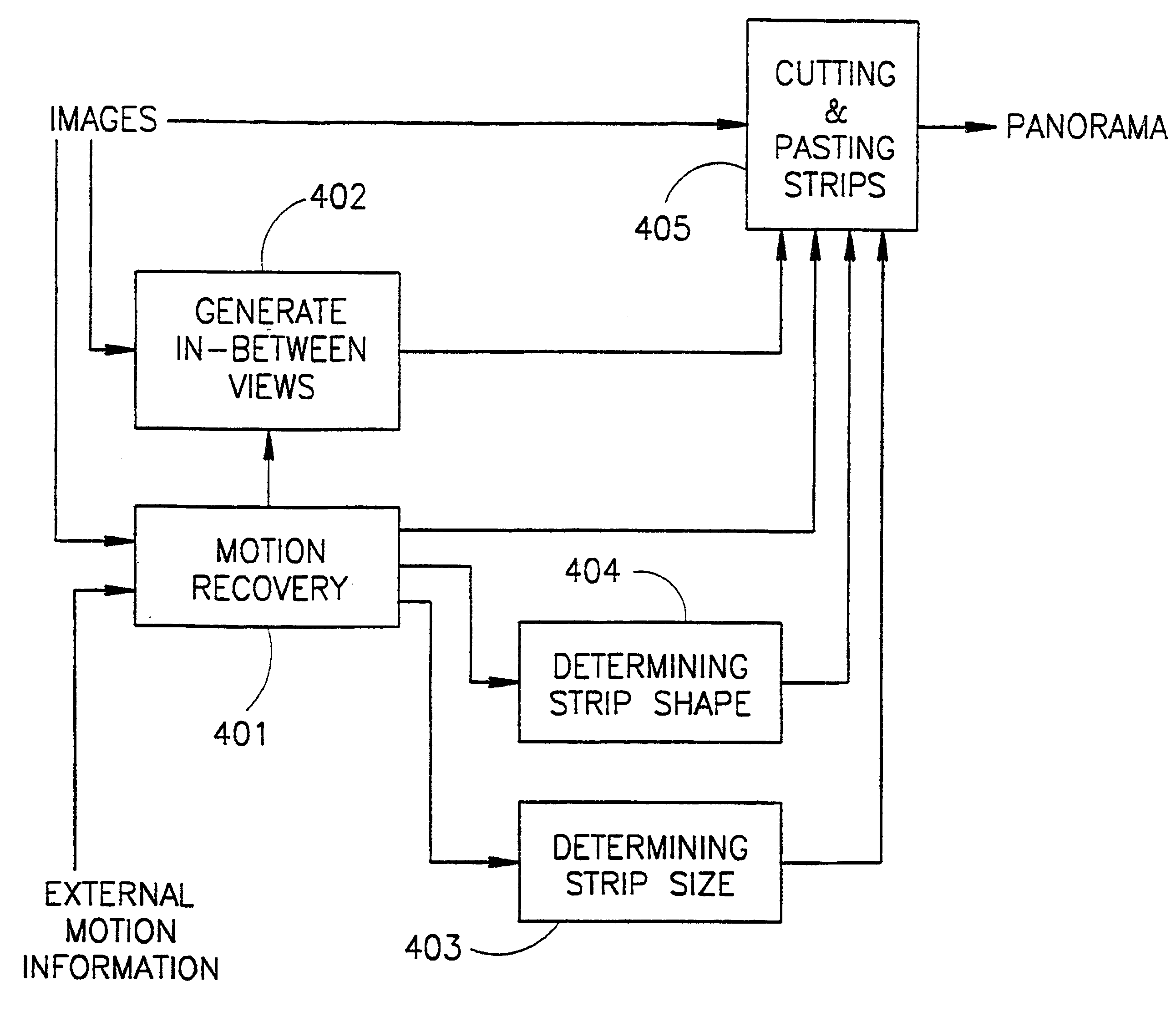
An example of strip shaping for the special case of affine motion will now be described. Affine motion is based on an affine transformation and affords a good approximation for many types of motion. Based on the detailed description given below it will be apparent to a person skilled in the art that other types of motion can be dealt with in a similar manner.

The affine transformation can be expressed as follows: ##EQU1##

where P.sub.n-1 =(x.sub.n-1, y.sub.n-1) and P.sub.n =(x.sub.n, y.sub.n) are the coordinates of corresponding points in images I.sub.n-1 and I.sub.n, and the parameters of the affine transformation A are (a, b, c, d, e, f). (u, v) is the optical flow vector as a function of position (x.sub.n, y.sub.n). The transformation A (and the optical flow) vary continuously along the sequence of images. Numerous methods exist to recover the parameters of an affine transformations [21, 18] and they will not be described here.

In accordance with the metho...


PUM


Abstract

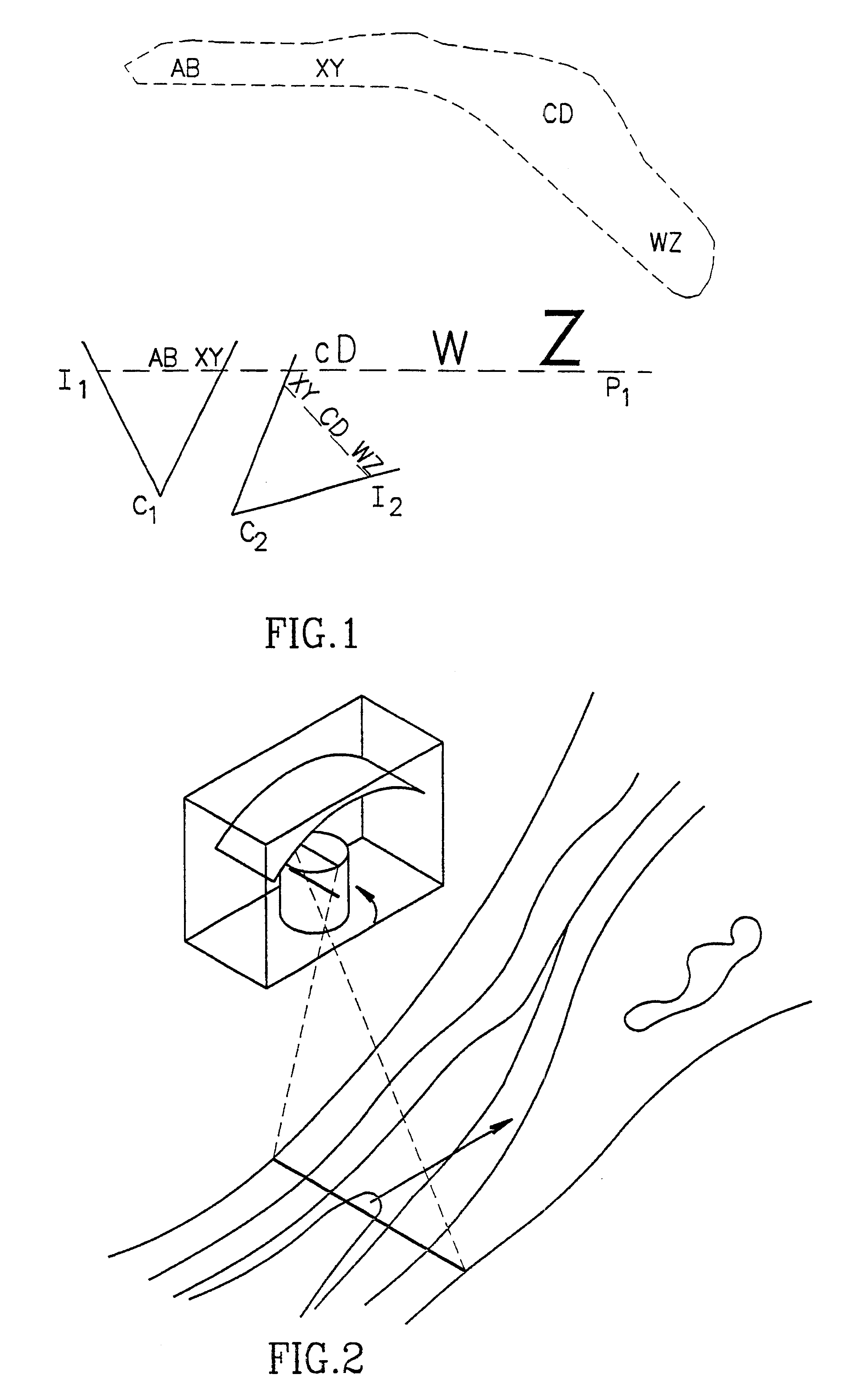
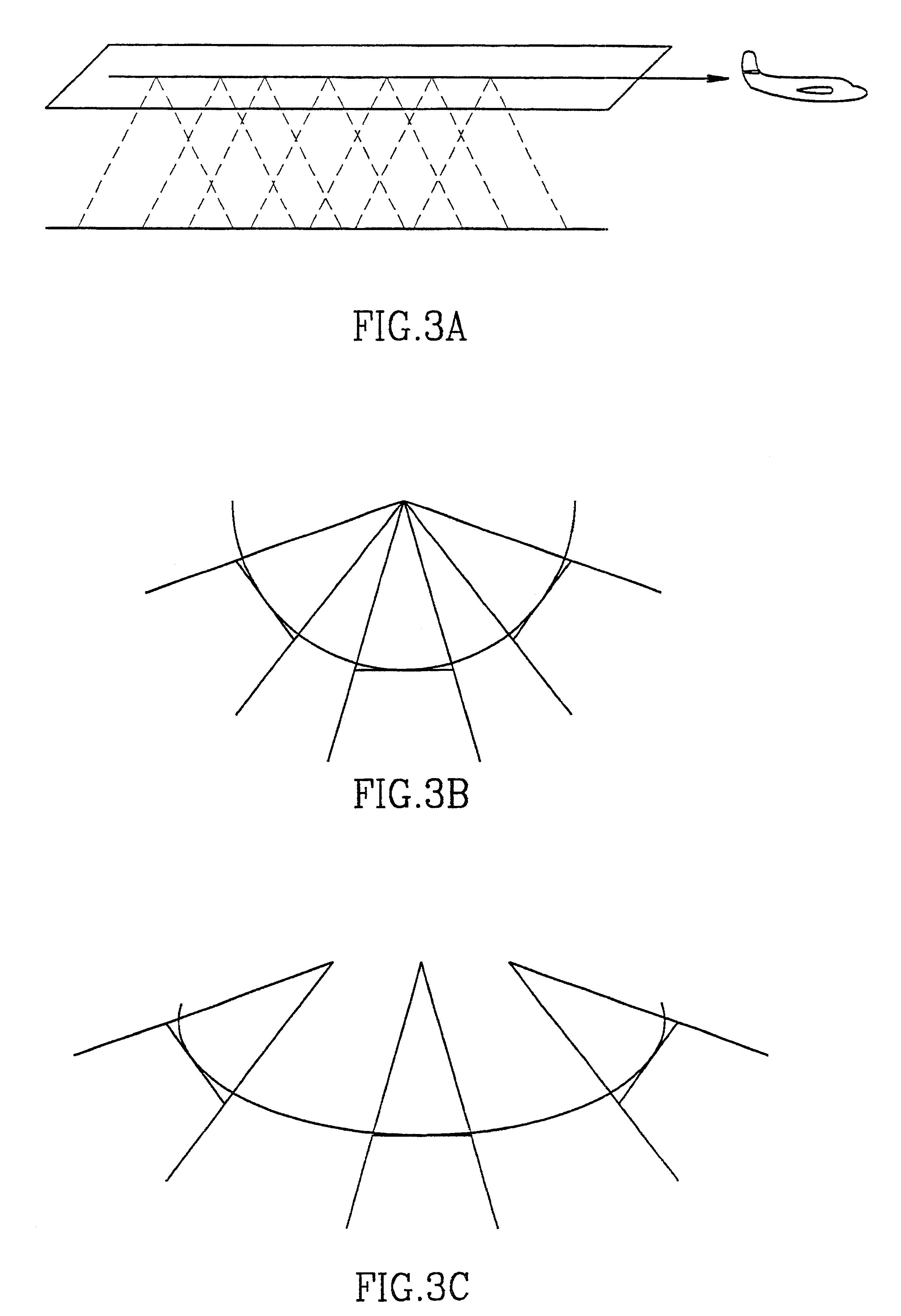
A method for combining a sequence of two-dimensional images of a scene to construct a panoramic mosaic of the scene has a sequence of images acquired by a camera with relative motion to the scene. The relative motion gives rise to an optical flow between the images. The images are warped so that the optical flow becomes substantially parallel to a direction in which the mosaic is constructed and pasted so that the sequence of the images is continuous for the scene to construct the panoramic mosaic of the scene. For this, the images are projected onto a three-dimensional cylinder having a major axis that approximates the path of an optical center of the camera. The combination of the images is achieved by translating the projected two-dimensional images substantially along the cylindrical surface of the three-dimensional cylinder.

Description

This invention relates to video image mosaicing for obtaining panoramic mosaics of a scene.PRIOR ARTPrior art references considered to be relevant as a background to the invention are listed below. Acknowledgement of the references herein shall not be inferred as meaning that these are in any way relevant to the patentability of the invention disclosed herein. Each reference by a number enclosed in square brackets and accordingly the prior art will be referred to throughout the specification by numbers enclosed in square brackets.[1] ARPA Image Understanding Workshop, Monterey, Calif., November 1994, Morgan Kaufmann.[2] Fifth International Conference on Computer Vision, Cambridge, Mass., June 1995, IEEE-CS.[3] IEEE Conference on Computer Vision and Pattern Recognition, San Francisco, Calif., June 1996.[4] P. J. Burt and E. H. Adelson. A multiresolution spline with application to image mosaics. ACM Trans. on Graphics, 2(4), pages 217-236, October 1983.[5] P. J. Burt and P. Anandan. I...

Claims


Application Information

Patent Timeline
IPC IPC(8): G06T3/00G03B37/00H04N5/262
CPCG06T3/4038
Inventor PELEG, SHMUELROUSSO, BENNY
Owner YISSUM RES DEV CO OF THE HEBREWUNIVERSITY OF JERUSALEM LTD
Learn More