
Structure of hemmed together metal plate materials

Inactive Publication Date: 2003-03-04
SANYO KIKO KK
View PDF14 Cites 104 Cited by
  • Summary
  • Abstract
  • Description
  • Claims
  • Application Information

AI Technical Summary

Benefits of technology

In accordance with the present invention, the inside rise portion formed at the edge portion of the inner panel in advance is telescopically fitted with the outside rise portion formed during complete hem forming of the outer panel, thereby assuring reliable retention without deflection between the inner panel and the outer panel. Accordingly, even in the case of applying adhesive, both panels will be securely retained until the adhesive cures. Particularly, since a sturdy structure is formed in a way of caulking with the inside and outside rise portions fitted with each other, it is possible to completely prevent relative movement between the panels at least in a direction parallel to the edge of the inner panel.

Problems solved by technology

Thus, since the hemmed together pamels are transported to an oven or the like for curing after the hemming process, the hemmed together panels are not always retained as they are during transport.
However, interlocking the hemmed together panels by spot welding has a problem of thermal distortion as a result of welding heat.
Also, in the method of dimple caulking, it is very difficult to make center alignment between the escape portion of a hemming die and the inner panel.
That is, it is very difficult to make the hemming die pressing direction match the dimple shape of the press die, and after all, the job has to be done at the site.
It is clear that generation of disalignment causes marks to remain on the outer surface of the outer panel.
Furthermore, in the hemming process, there is no problem because of forming a dimple on the inner panel in advance, but the outer panel itself has a shape (for example, in the case of a door panel, it has a substantial curvature at the top close to the roof), there exists a problem that a dimple cannot be properly formed by a press that makes a vertical motion.
Consequently, adaptable portions will be very much limited.
In this case, however, the laser beam is applied to the spherical surface of the dimple and it is very difficult to control the height of the dimple and also to release the gas decomposed from the adhesive due to heat generated during laser welding or to control dimple clearance.
In a conventional method of dimple caulking, a spherical dimple is formed by pressing an inner panel, and an outer panel is similarly pressed and formed along the spherical profile, which will not assure a tight fitting finish.

Method used


Image

  • Structure of hemmed together metal plate materials
  • Structure of hemmed together metal plate materials
  • Structure of hemmed together metal plate materials

Examples


Embodiment Construction

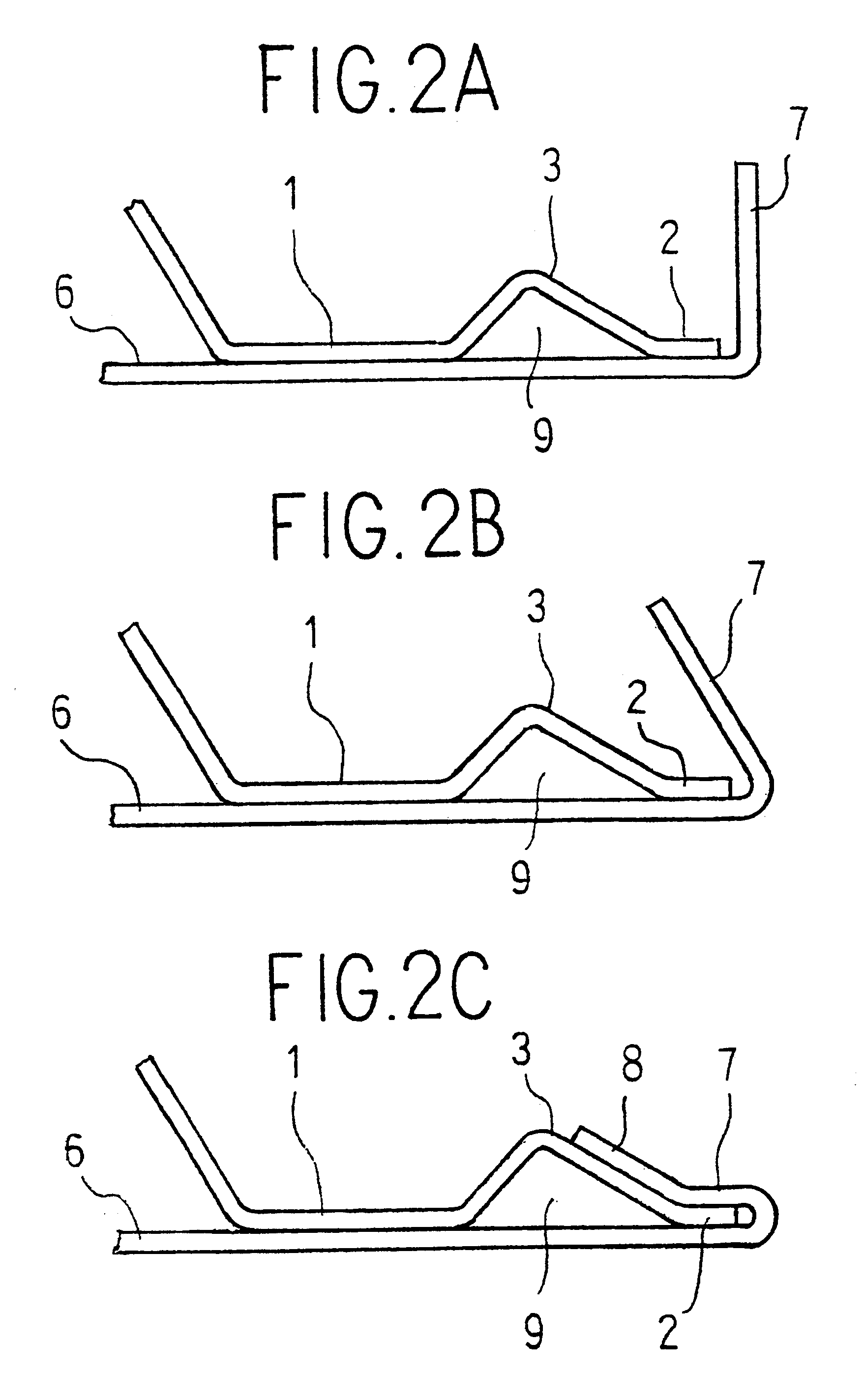
In FIGS. 1A.about.1C is shown a hemming structure of an outer plate for automobiles, comprising an inner panel 1 and an outer panel 6 bonded to each other by hemming at edge portions 2 and 7.

A process of hemming is executed by placing the inner panel 1 on the outer panel 6 and by bending the edge portion 7 of the outer panel 6 over the edge portion 2 of the inner panel 1. Generally, there is provided an adhesive layer of thermosetting resin type between both edge portions 2 and 7. Here, the inner panel 1 is formed in such a manner that the inner side 5 located inward the edge portion 2 is bent to make the inner side apart from the outer panel 6.

At the edge portion 2 of the inner panel 1 is formed an inside rise portion 3 projecting away from the outer panel. Here, the cross-section of the inside rise portion 3 is inverted V-shaped, and a triangular space 9 is formed between the inside rise portion and the outer panel 6. The slope on an edge 4 side of the inner panel 1 is a plane dow...


PUM

PropertyMeasurementUnit
Heightaaaaaaaaaa
Heightaaaaaaaaaa
Structureaaaaaaaaaa

Abstract

In a hemming structure of metal plate material with an edge portion (7) of an outer panel (6) hemmed over an edge portion (2) of an inner panel (1), the edge portion (2) of the inner panel (1) has an inside rise portion (3) having a surface plane (3') down-sloping towards an edge (4) thereof and the edge portion (7) of the outer panel (6) has an outside rise portion (8) telescopically fitted with the inside rise portion (3), a back plane (8') of the outside rise portion (8) abutting on the surface plane (3') of the inside rise portion (3).

Description

1. Field of the InventionThe present invention relates to a structure of hemmed together metal plate materials, for use of hemming of, for example, outer plates for automobiles such as engine hoods and door panels.2. Description of Related ArtA hem structure of an outer plate for automobiles is usually formed by folding an edge of an outer panel over edge of an inner panel with a sealant or adhesive applied therebetween for the purpose of bonding. When a thermosetting resin is used as the adhesive, it is heated and cured in an oven or the like after the hemming process.Thus, since the hemmed together pamels are transported to an oven or the like for curing after the hemming process, the hemmed together panels are not always retained as they are during transport. Accordingly, in order to retain the hemmed together pamels until the adhesive completely cures, it has been a conventional manner, for example, to dimple caulking or coining for the purpose of preventing relative movements b...

Claims


Application Information

Patent Timeline
IPC IPC(8): B21D39/02
CPCB21D39/021Y10T428/12347Y10T428/12375Y10T29/49936Y10T428/12264
Inventor ASAI, KATSUHIKOISHIHARA, KOICHI
Owner SANYO KIKO KK
Learn More