
Warping geometric objects

a technology of geometric objects and sets of geometric objects, applied in static indicating devices, instruments, animations, etc., can solve problems such as distortion caused by paper stretching, folding, scaling, and different regions of models

Inactive Publication Date: 2003-01-07
TELE ATLAS NORTH AMERICA
View PDF11 Cites 106 Cited by
  • Summary
  • Abstract
  • Description
  • Claims
  • Application Information

AI Technical Summary

Problems solved by technology

Such distortions are often localized, with different regions of the model being distorted differently.
In paper models, distortion can be caused by paper stretching, folding, and scaling.
In electronic models, distortion can be caused when the model is transformed into digital form.
However, such a method is inadequate, because it does not provide for maintaining the topology of the original models in the new model.
However, this global approach does not provide for eliminating local distortions, which constitute many of the distortions that are encountered.

Method used


Image

  • Warping geometric objects
  • Warping geometric objects
  • Warping geometric objects

Examples


Embodiment Construction

has been presented for purposes of illustration and description. It is not intended to be exhaustive or to limit the invention to the precise form disclosed, and obviously many modifications and variations are possible in light of the above teaching. The described embodiments were chosen in order to best explain the principles of the invention and its practical application to thereby enable others skilled in the art to best utilize the invention in various embodiments and with various modifications as are suited to the particular use contemplated. It is intended that the scope of the invention be defined by the claims appended hereto.


PUM


Abstract

A system is disclosed for warping models made from geometric objects, such as electronic maps, to correct local distortions in the models without compromising model topology. A set of transformation functions are derived from relationships between points in a first model that match points in a second model. The transformation functions are then applied to the points in the first model to generate a new model with reduced distortion. In order to provide for reducing local distortions, warping is applied to selected corresponding regions of the first model and the second model by triangulating these regions and generating transformation functions for each corresponding pair of triangles. Topology preservation is achieved by identifying matching points in the first model and the second model that have a potential for causing topology deviations. Such matching points are then excluded from the process of developing transformation equations to be used in the warping process. Matching points with potential for causing topology deviations are identified by triangulating matching points in the selected regions of the first model and the second model and analyzing the resulting triangles.

Description

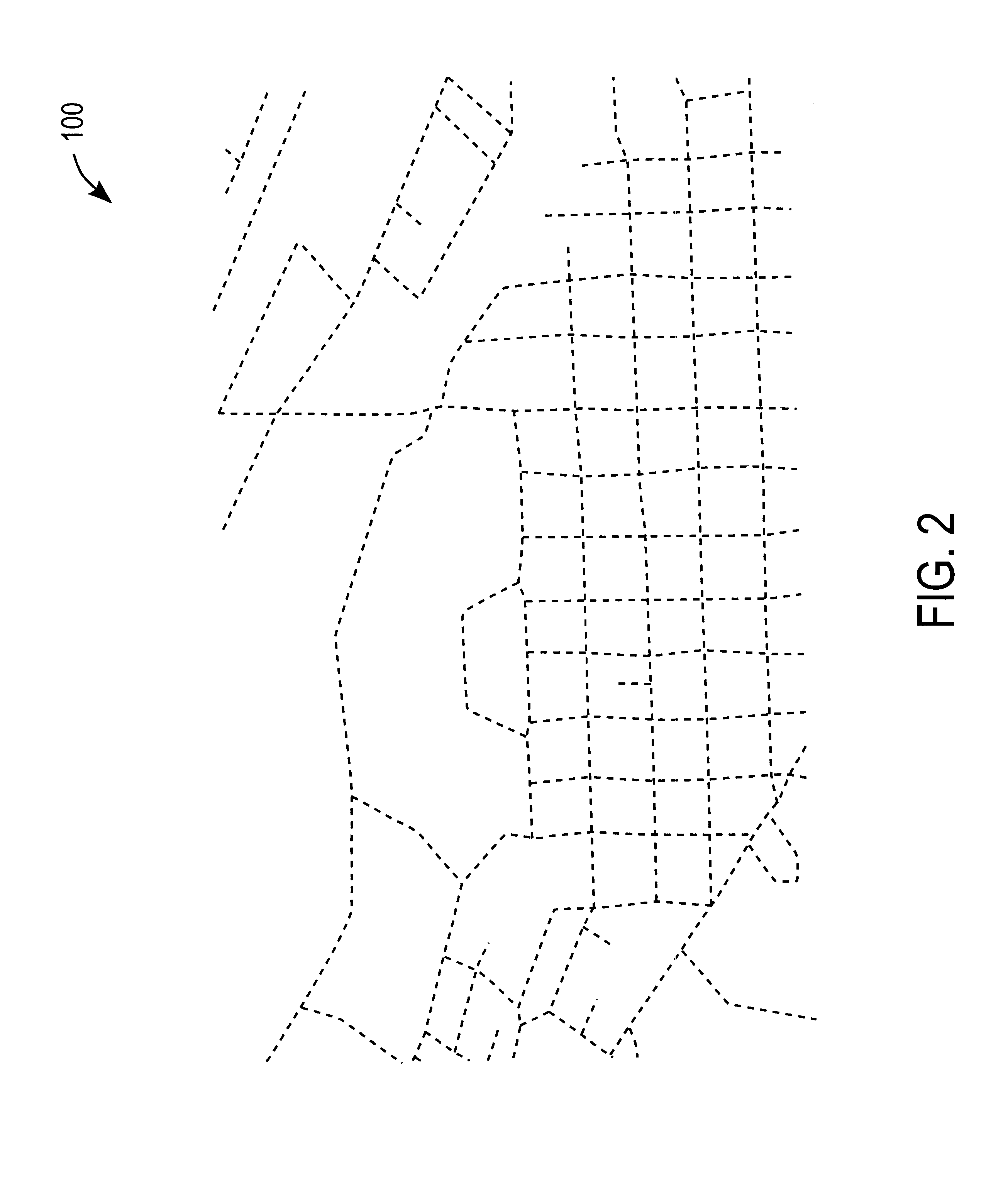
1. Field of InventionThe present invention is directed toward the field of warping sets of geometric objects.2. Description of Related ArtPhysical areas are often modeled using geometric objects. Examples of such physical areas include a geographic region and a building's floor plan. One example of a model using two-dimensional geometric objects is a map of a geographic region, such as a city.FIG. 1 illustrates a map that is formed by a set of geometric objects. The objects in FIG. 1 include points 60-70, arcs 80-91, and polygons 50-51. Each arc 80-91 represents a road and is bounded at each of its ends by a point. For example, arc 80 is bounded at one end by point 60 and at another end by point 62. Each arc can be co-bounded by one or two polygons. For example, arc 86 is co-bounded by polygons 50 and 51, while arc 85 is only co-bounded by polygon 50. Each polygon 50 and 51 is formed by a set of arcs that define the boundary of the polygon. For example, polygon 50 is defined by boun...

Claims


Application Information

Patent Timeline
IPC IPC(8): G06T17/20G06T17/50G06K9/00G06T17/05
CPCG06K9/00476G06T17/205G06T17/20G06T17/05G06V30/422
Inventor LIU, HONGCHEKUTTIKKAD, SHYAM
Owner TELE ATLAS NORTH AMERICA
Learn More