
Stadium seat

Inactive Publication Date: 2003-01-07
ROMERO KARDEL
View PDF14 Cites 77 Cited by
  • Summary
  • Abstract
  • Description
  • Claims
  • Application Information

AI Technical Summary

Benefits of technology

Therefore, one object of this invention is to provide an improved stadium seat that is comfortable and supportive of the person sitting in the seat.
Another object of this invention is to provide an improved stadium seat that is stable and less prone to become unattached to the stadium bleacher by the ordinary movements of a person sitting in the seat.
Still another object of this invention is to provide an improved stadium seat that will not mar or otherwise damage the bleacher through its use.
Accordingly, a conventional foldable, portable stadium seat having a backrest member pivotly mounted to a seat member attached to a stadium bleacher by one or more spring biased hook members, preferably at least two, is improved by using a forward, downward sloping cushioned seat mounted on a stiff tubular frame. In a preferred embodiment the seat comprises a stiff tubular frame to which the cushion is attached. A particularly preferred frame is one constructed from Schedule 40, one-inch aluminum tubing, or other tubing material having similar stiffness characteristics. In another preferred embodiment, the seat member further comprises a support panel positioned between the cushion and the frame. The support panel extends over the frame and is constructed of material having sufficient rigidity and strength to prevent the cushion from being pushed through the frame when a person sits on the cushion.

Problems solved by technology

In addition, these prior art stadium seats are prone to become unattached to the bleacher, particularly when a person pivots in the seat or leans back with too much force.
This not only is a nuisance, but can also cause harm to the user in certain circumstances.

Method used


Image

  • Stadium seat
  • Stadium seat
  • Stadium seat

Examples


Embodiment Construction

Without any intent to limit the scope of this invention, reference is made to the figures in describing the preferred embodiments of the invention.

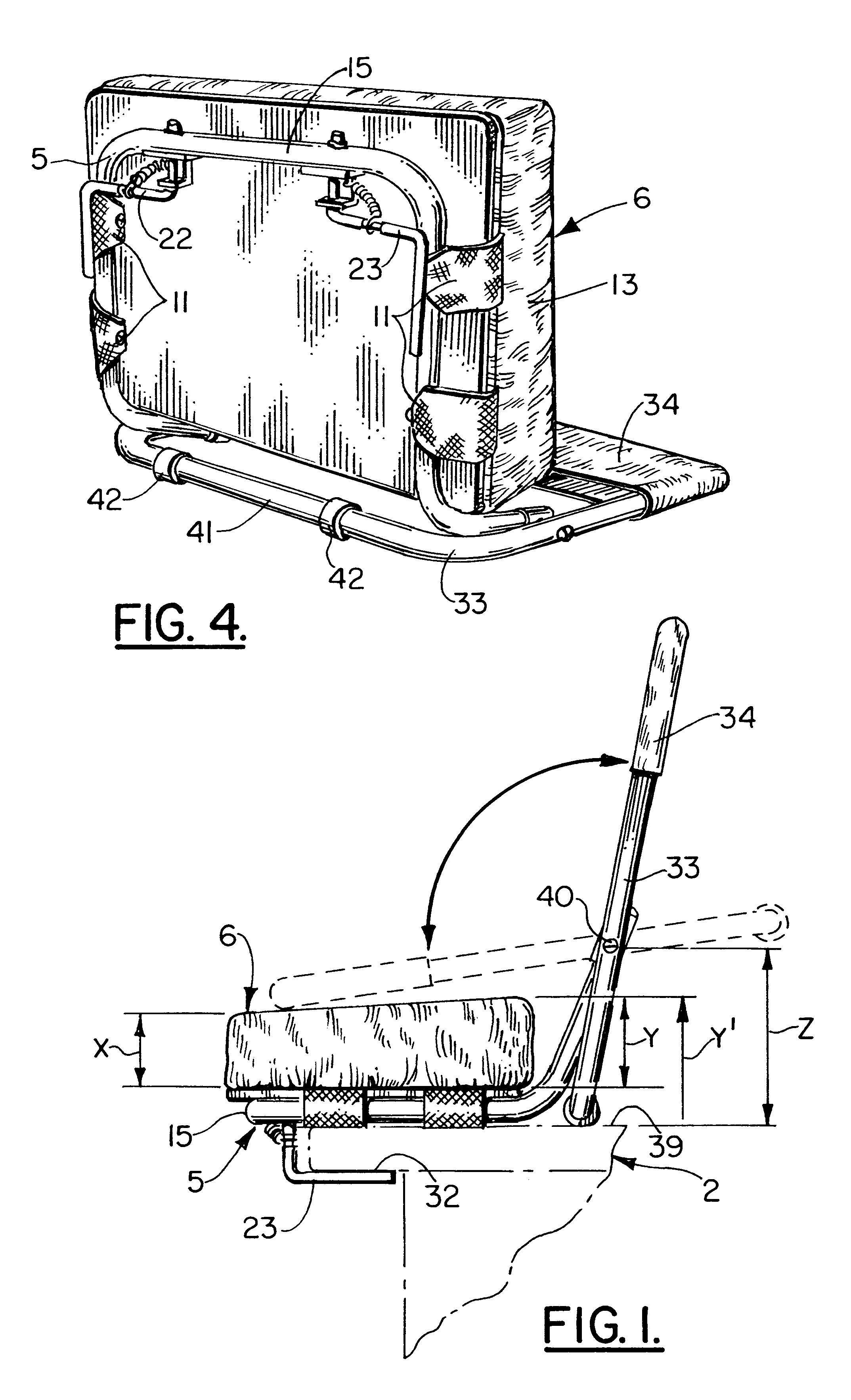
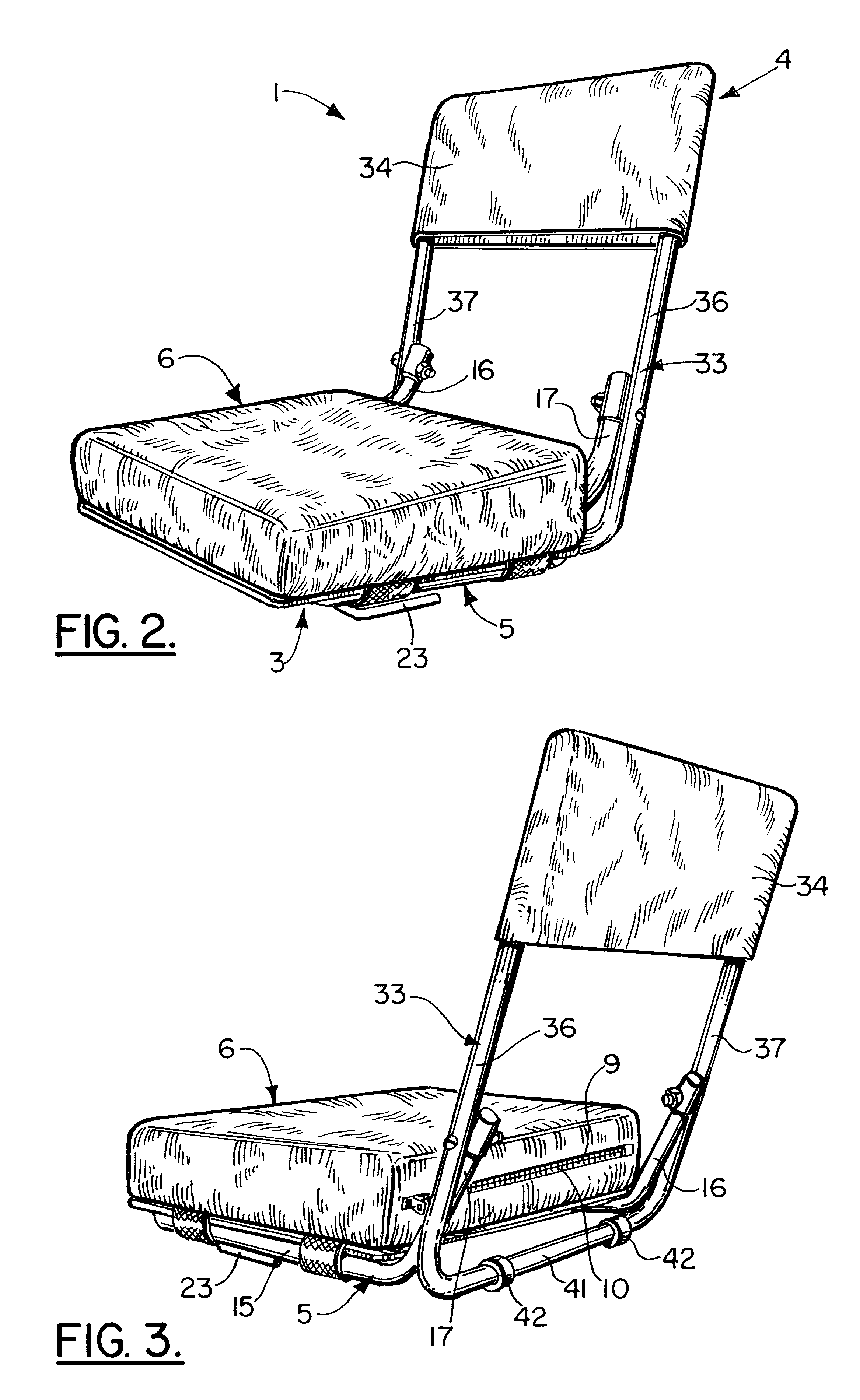
FIG. 1 illustrates a preferred embodiment of a stadium seat constructed in accordance with this invention. More particularly, stadium seat 1 is constructed for attachment to a conventional stadium bleacher 2, and comprises a seat assembly 3 attached to backrest assembly 4 in a manner permitting the backrest assembly 4 to be folded over seat assembly 3 as illustrated by the phantom lines in FIG. 1. In this folded over position cross tubing section 41 serves as a carrying handle for stadium seat 1. Additionally, the stadium seat 1 in this position is compact for easy storage.

In a preferred embodiment the seat assembly 3 comprises a frame 5 to which is attached a cushion 6 whose front height "x" is less than its back height "y" (see FIG. 4). In a more preferred embodiment "x" will be about 2 inches and "y" will be about 3 inches. It has been...


PUM


Abstract

An improved foldable, portable stadium seat providing greater support, comfort, stability, and durability through the use of a forward, downward sloping cushioned seat formed in part by a stiff tubular frame having a U-shaped section and two vertically extending straight sections to which is pivoted mounted to a backrest frame of a backrest at a position permitting the backrest frame to contact the bleacher when the backrest is in its vertical most position.

Description

A. BACKGROUND OF THE INVENTION1. Field of the InventionThis invention relates in general to foldable, portable stadium seats attachable to a stadium bleacher.2. Prior ArtFoldable, portable stadium seats are well known in the art. One of the most common comprises a seat member attached to a backrest member pivotly connected to fold against one another when not in use. These seats are attached to a stadium bleacher by a hook member held in position against the bleacher generally by a spring. Examples of such seats are illustrated in U.S. Pat. Nos. 2,220,865, 2,509,420, 2,736,365, 3,066,980, 3,560,047, 3,994,529, 4,715,652, and 5,580,130.Although the prior art stadium seats to improve the comfort of the user, there remains a need for improved comfort and increased back support. In addition, these prior art stadium seats are prone to become unattached to the bleacher, particularly when a person pivots in the seat or leans back with too much force. This not only is a nuisance, but can al...

Claims


Application Information

Patent Timeline
IPC IPC(8): A47C1/00A47C1/16A47C5/00A47C5/10
CPCA47C5/10A47C1/16
Inventor ROMERO, KARDEL
Owner ROMERO KARDEL
Learn More