Eureka AIR delivers breakthrough ideas for toughest innovation challenges, trusted by R&D personnel around the world.

X-ray computed tomography method and apparatus

a computed tomography and x-ray technology, applied in the direction of material analysis using wave/particle radiation, instruments, nuclear engineering, etc., can solve the problem of inability to achieve the incidence of x-rays for dental arch from a complete normal direction, long radiograph and analysis time,

Inactive Publication Date: 2002-12-10
NIHON UNIVERSITY +1
View PDF2 Cites 105 Cited by
  • Summary
  • Abstract
  • Description
  • Claims
  • Application Information

AI Technical Summary

Problems solved by technology

In addition, it takes long to radiograph and analyze the test data.
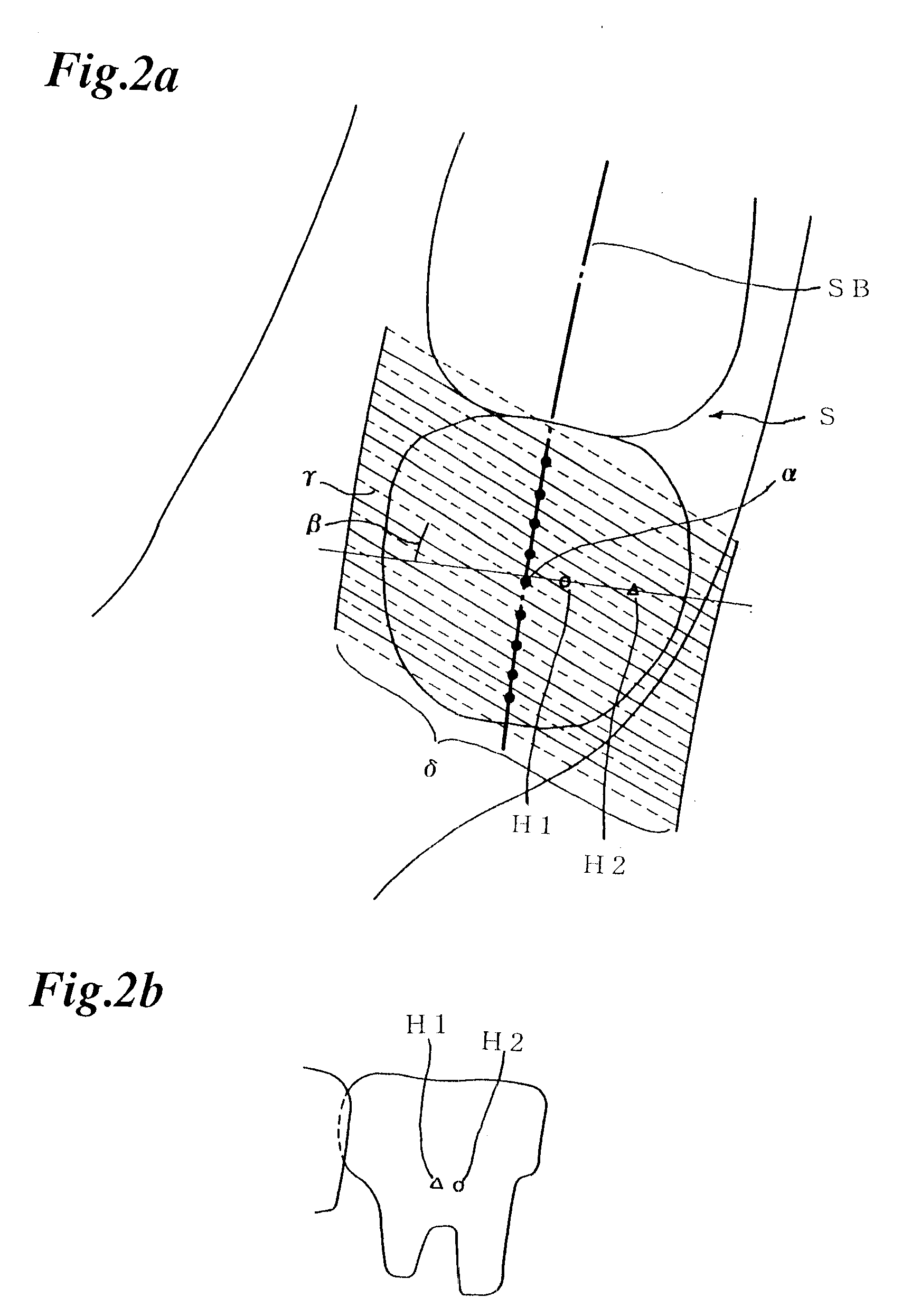
But the panoramic X-ray images produced by the above mentioned method has one problem: as the production method of panoramic X-ray images is limited to the method shown in FIG. 24b, if there are any foreign materials H1 and H2 in the direction of a normal line LC, they are overlapped in the obtained panoramic X-ray image shown in FIG. 24c and cannot be distinguished.
Another problem is that as this apparatus was not made for a computer tomography but for a conventional picturing of sectional images, it also requires the rotating center of the rotary arm to be moved along the specified loci during picturing, which needs a complex driving mechanism.
Furthermore, X-ray incidence for a dental arch from a complete normal direction can't be achieved.
In the prior panoramic X-ray image, because front teeth are inclined for a sectional image layer, images in which adjacent teeth are overlapped are obtained or images of accurate size can't be obtained.

Method used


Image

  • X-ray computed tomography method and apparatus
  • X-ray computed tomography method and apparatus
  • X-ray computed tomography method and apparatus

Examples


third embodiment

The X-ray CT apparatus in a twelveth embodiment is to achieve the CT method of and have the same effect as that of the

The X-ray CT apparatus in a thirteenth embodiment is to achieve the CT method of and have the same effect as that of the fourth embodiment.

The X-ray CT apparatus in a fourteenth embodiment is to achieve the CT method of and have the same effect as that of the fifth embodiment.

sixth embodiment

The X-ray CT apparatus in a fifteenth embodiment is to achieve the CT method of and have the same effect as that of the

seventh embodiment

The X-ray CT apparats in a sixteenth embodiment is to achieve the CT method of and have the same effect as that of the


PUM


Abstract

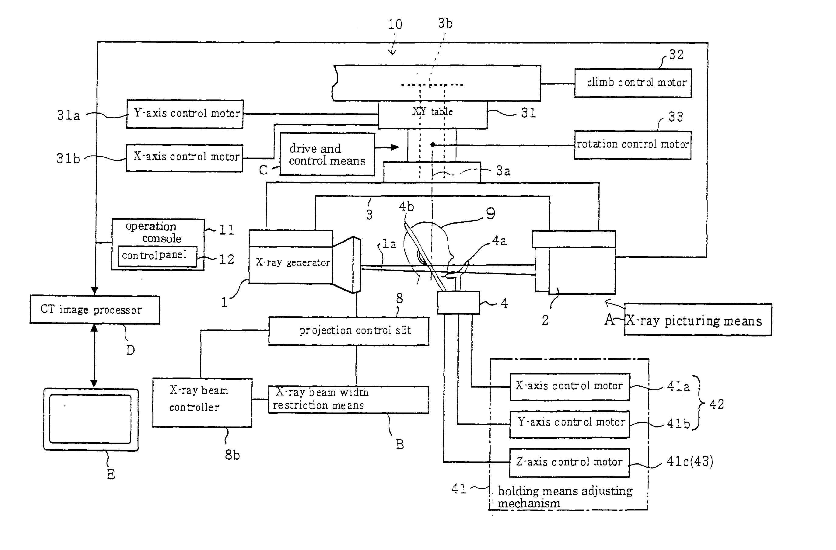
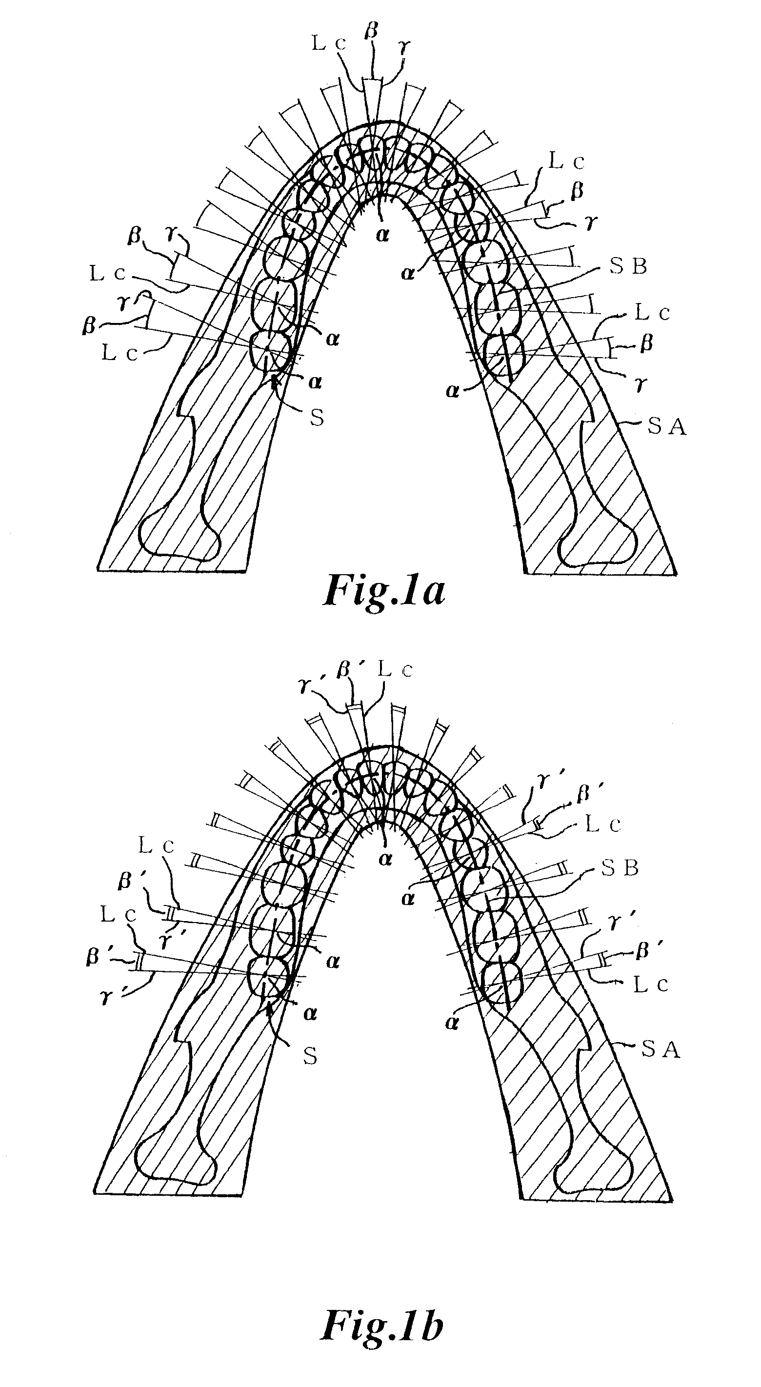
An X-ray computed tomography method and apparatus for obtaining a panoramic X-ray image seen from a direction of a projection line gamma (gamma') of a curved sectional area SA by expanding calculation results of three-dimensional distribution information of X-ray absorption coefficient on the projection line gamma (gamma') intersecting at a specified angle beta (beta') for any regions alpha of the panoramic sectional image layer SB on a two-dimensional plane based on the three dimensional distribution information of X-ray absorption coefficient of the curved sectional area SA obtained by a X-ray CT.

Description

1. Field of the InventionThe present invention relates to an X-ray computed tomography (CT) method and apparatus for obtaining panoramic X-ray images of an object to be examined seen from an optional direction by radiating a conical X-ray beam on a part of the object to be examined.2. Prior ArtA method of obtaining a panoramic X-ray image known as X-ray computer tomography (CT) has been widely used in medical practice as for diagnosis. This method involves radiating X-rays on the object from all around, followed by analyzing a three-dimensional absorption coefficient distribution information, namely a three-dimensional distribution information of an X-ray absorption coefficient, on the X-rayed object from the projection data by the Radon theory as widely known, thereby obtaining a sectional image of object.The prior art X-ray CT is a technique in which a fan-shaped X-ray beam relatively wide in the direction of rotation and thin is radiated on the object from around at a depth and t...

Claims


Application Information

Patent Timeline
Patent Type & Authority Patents(United States)
IPC IPC(8): A61B6/14A61B6/51
CPCA61B6/14A61B6/51
Inventor ARAI, YOSHINORISUZUKI
Owner NIHON UNIVERSITY
Why Eureka
Eureka Blog
Learn More