
Representing a color gamut with a hierarchical distance field

Inactive Publication Date: 2002-11-19
MITSUBISHI ELECTRIC RES LAB INC
View PDF5 Cites 77 Cited by
  • Summary
  • Abstract
  • Description
  • Claims
  • Application Information

AI Technical Summary

Benefits of technology

Distance maps can reduce aliasing artifacts in sampled volumes, but because distance maps are sampled on a regular grid, they still require a trade-off between memory requirements and the finest detail that can be represented. In addition, volume rendering of distance maps is slow, limiting real-time interactivity. The three-color octree could be used with distance maps to improve rendering rates and reduce the amount of storage necessary for object interiors and exteriors.
As an advantage, the hierarchical distance field enables one to test inside vs. inside of the device color gamut correct to within a small error tolerance, and measure of how close a color is to the gamut surface within a surface representation error. This information can be used to replace colorts that are outside the gamut with colors inside the device color gamut. Furthermore, the hierarchical distance field representation uses less memory than prior art distance field representation since the present representation adapts to the detail of the color gamut surface.

Problems solved by technology

Each of the three common surface representations discussed above has limitations.
Parametric surface models do not represent interiors and do not provide an easy means for detecting inside vs. outside.
Implicit surfaces do not have a natural conversion from the expression for the surface to points in 3D space and hence they are harder to render than parametric surfaces.
These high sampling rates require large amounts of memory and long rendering times.
In addition, volume rendering of distance maps is slow, limiting real-time interactivity.
However, existing density map methods are problematic because of excessive smoothing of edges and corners and because of data storage and rendering requirements.
In addition, because the resolution of the sampled data is pre-determined, the detail that can be achieved during editing is limited before editing begins.

Method used


Image

  • Representing a color gamut with a hierarchical distance field
  • Representing a color gamut with a hierarchical distance field
  • Representing a color gamut with a hierarchical distance field

Examples


Embodiment Construction

Introduction Hierarchical Distance Fields

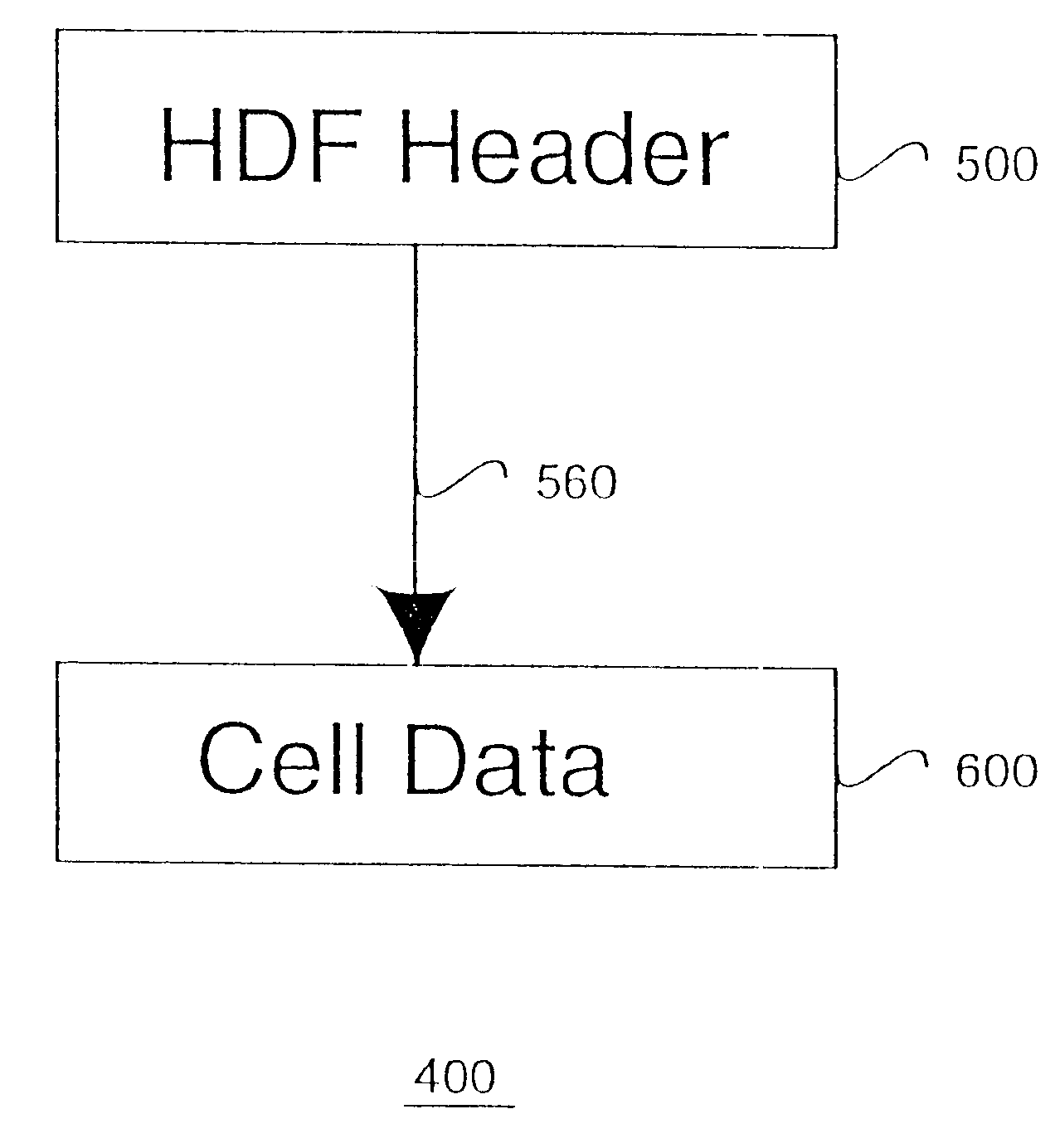
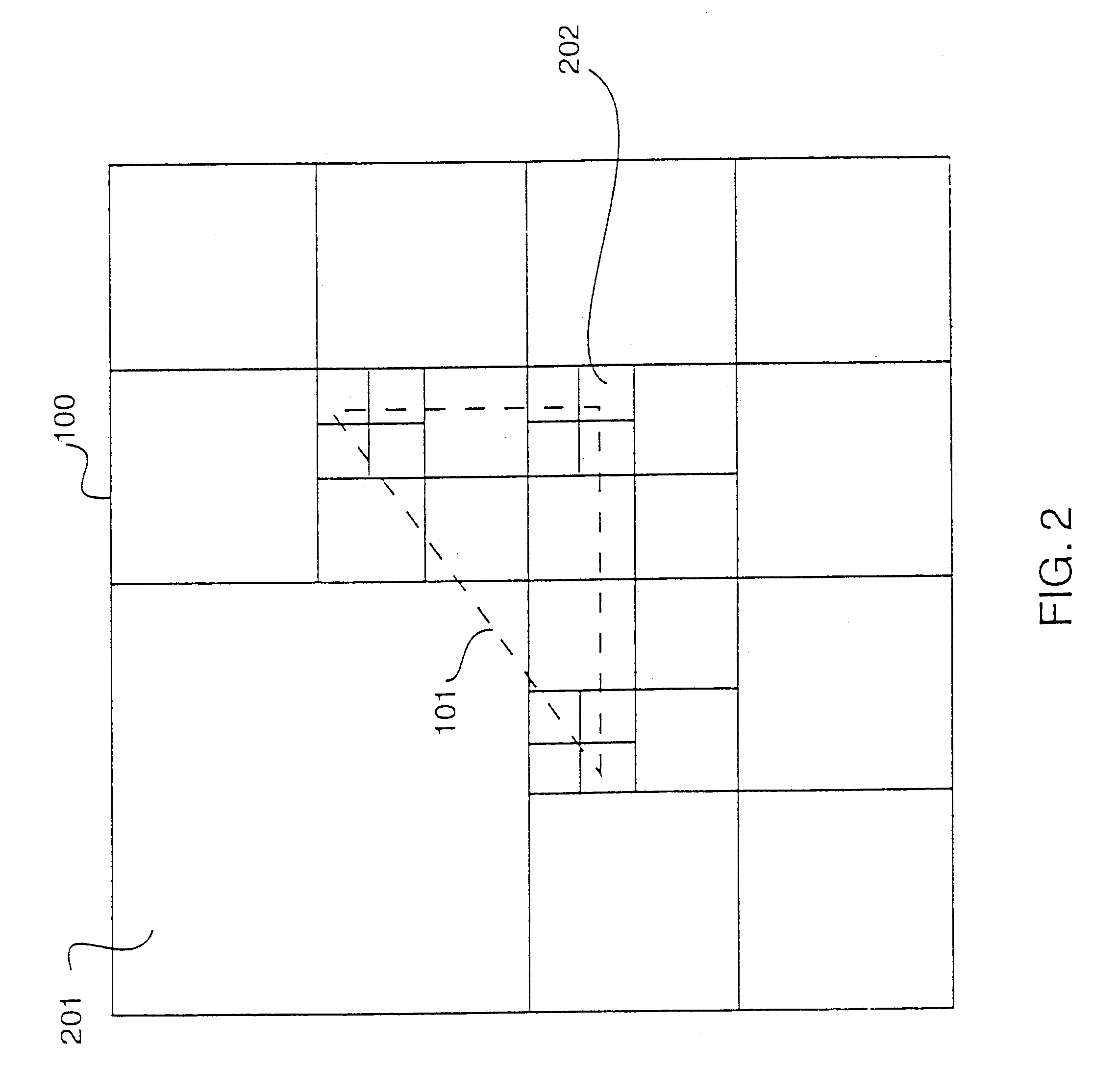
The present invention provides detail-directed hierarchical distance fields (HDFs). In the following, the data structures used to store these distance fields in a memory are described first. Then, fundamental operations that can be applied to the data structures will be recited, followed by details on methods for generating, converting, rendering and editing the data structures. Finally, a specific applications for sculpting and color management with the detail-directed hierarchical distance fields is given.

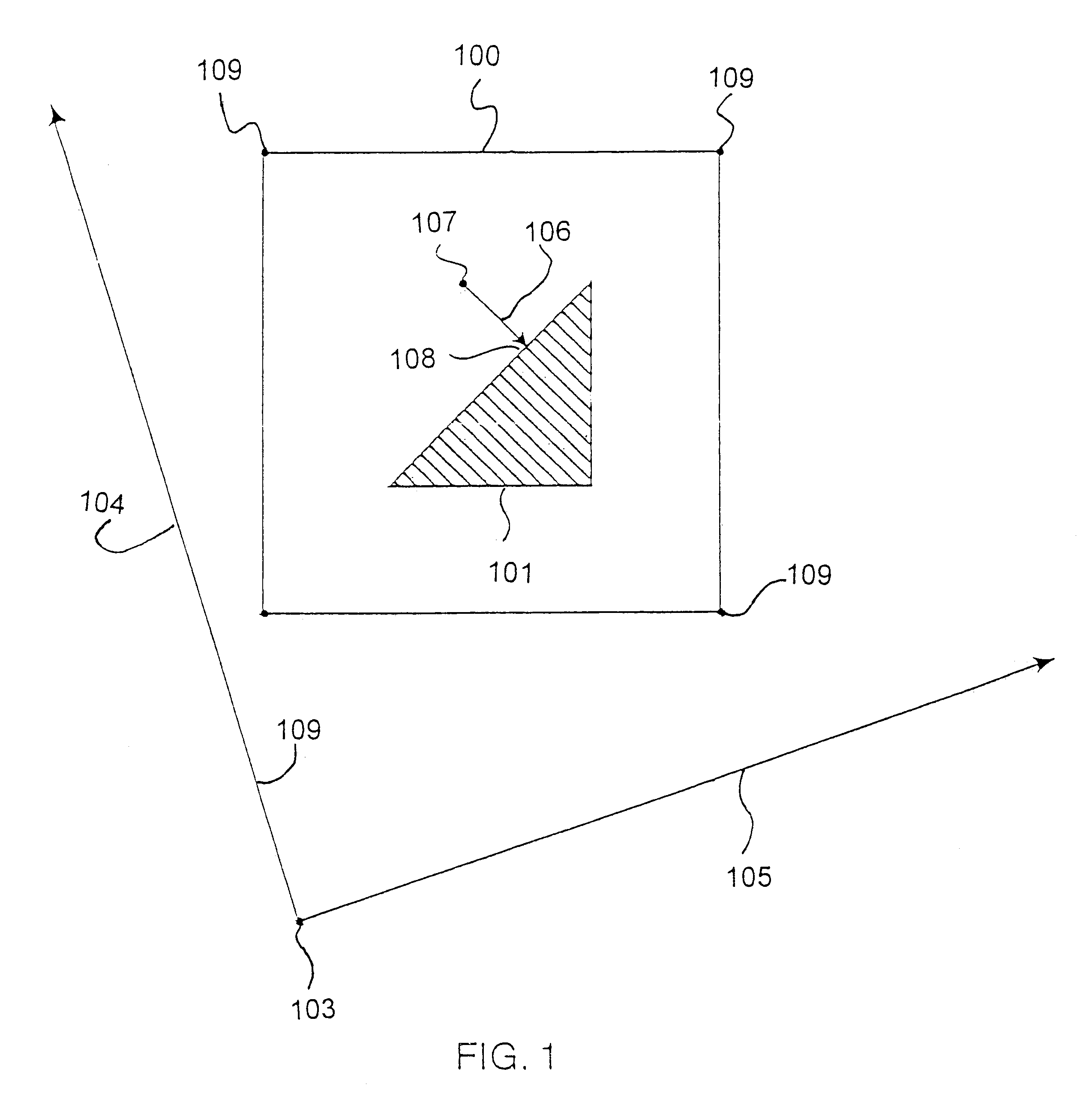
FIG. 1 shows a bounding box 100 enclosing a portion of a distance field associated with an object 101. In 2D, the bounding box 100 is located in some world coordinate space defined by an origin 103 and axes 104 and 105. The space enclosed by the bounding box is defined in terms of the coordinates of the world coordinate space. The size and location of the bounding box is specified by its vertices 109.

In this example, the space is two-dimen...


PUM


Abstract

The invention provides a method for representing a device color gamut as a detail directed hierarchical distance field. A distance field representing the device color gamut is enclosed with a bounding box. The enclosed distance field is partitioned into a plurality of cells. Each cell has a size corresponding to detail of the continuous distance field and a location with respect to the bounding box. A set of values of the enclosed distance field is sampled for each cell. A method for reconstructing the portion of the distance field enclosed by the cell is specified. The size, the location, the set of values, and the method for reconstructing is stored in a memory to enable reconstruction of the device color gamut by applying the reconstruction methods of the cells to the values.

Description

The invention relates generally to the field of color reproduction, and more particularly to accurately converting and rendering colors in output devices having only a limited range of colors.Surface RepresentationsA representation of "shape" of an object or model is required in many fields such as computer-aided design and manufacturing, computational physics, physical modeling, and computer graphics. Three common representations for shape are parametric surface models, implicit surfaces, and sampled volume data.Parametric Surface ModelsParametric surface models define the surfaces of an object as a collection of primitives such as polygons, spline patches, or subdivision surfaces that are defined parametrically. Most graphics systems use a parametric representation. As stated by Alyn Rockwood in "The displacement method for implicit blending surfaces in solid models," ACM Transactions on Graphics, Vol. 8, No. 4, 1989, "parametric surfaces are usually easier to draw, tessellate, su...

Claims


Application Information

Patent Timeline
IPC IPC(8): G06T11/20G06T15/08G06T1/00G06T17/00H04N1/46H04N1/60
CPCG06T11/206
Inventor PERRY, RONALD N.FRISKEN, SARAH F.JONES, THOUIS R.
Owner MITSUBISHI ELECTRIC RES LAB INC
Learn More