
Apparatus and method for waste water treatment

a waste water treatment and apparatus technology, applied in water/sewage multi-stage treatment, separation processes, membranes, etc., can solve the problems of excessive sludge drawn out of the system, limited bod volume to the process line, and inability to meet the requirements of aeration tank size,

Inactive Publication Date: 2002-10-08
KURARAY CO LTD
View PDF15 Cites 25 Cited by
  • Summary
  • Abstract
  • Description
  • Claims
  • Application Information

AI Technical Summary

Problems solved by technology

One problem with the conventional activated sludge process is that the BOD volume load to the process line is limited to the range falling between 0.3 and 0.8 kg / m.sup.3.day or so.
In the process, therefore, large-size aeration tanks are inevitable.
Another problem with it is that the excessive sludge must be drawn out of the system and must be treated in an additional line.
In the activated sludge process, if waste water is treated under an elevated BOD volume load, its treatment is often insufficient.
If so, in addition, the activated sludge will poorly flocculate and, as a result, continuously running the process line will be impossible.
However, such a large-size tank is unfavorable.
In addition, in such a case, the sludge will form fine particles and produces another problem in that it could not be separated from the treated water through spontaneous flocculation.
Therefore, the problem with the carrier process is that it requires an additional cost for the flocculant and that the floc must be further treated in an additional line.
In case where an ordinary activated sludge process line is run under such a low sludge load, the sludge therein will disperse and could not spontaneously flocculate, thereby producing a problem in that the sludge is difficult to separate from the treated water.
This is because, since the resin membranes have a high degree of hydrophilicity, SS components are difficult to adhere onto them and, even when having adhered onto them, the adhered SS components are readily peeled off from them.
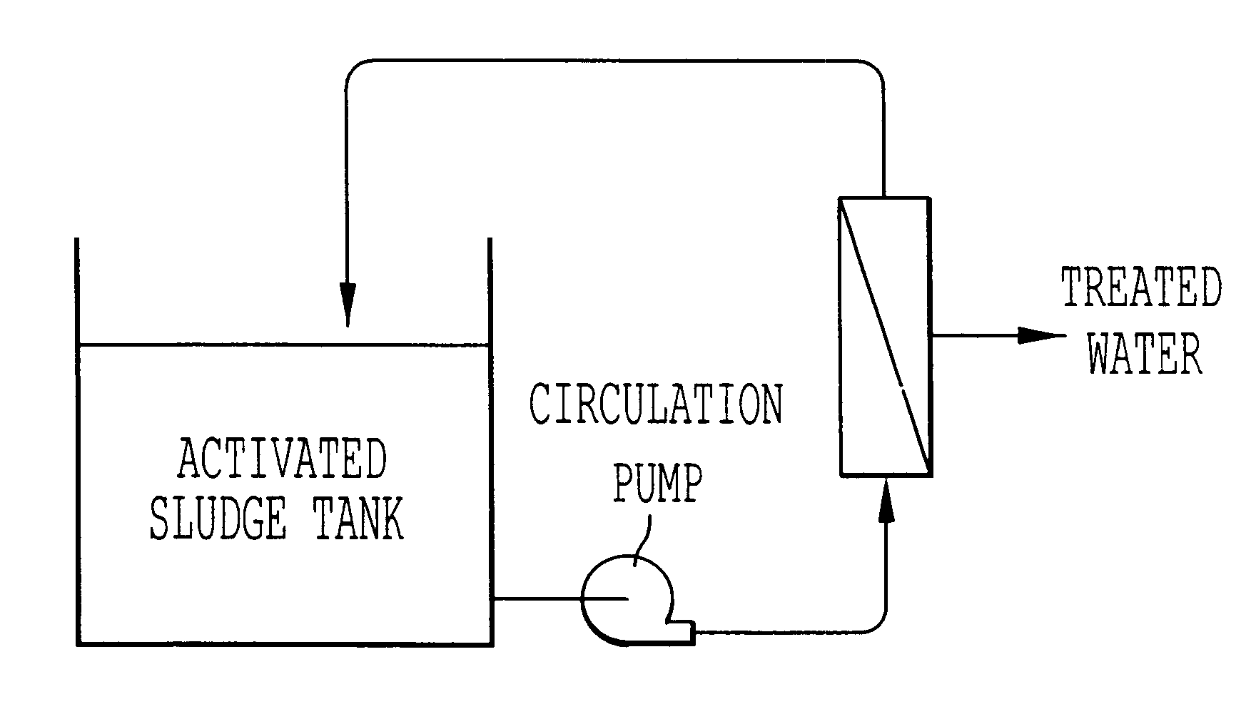
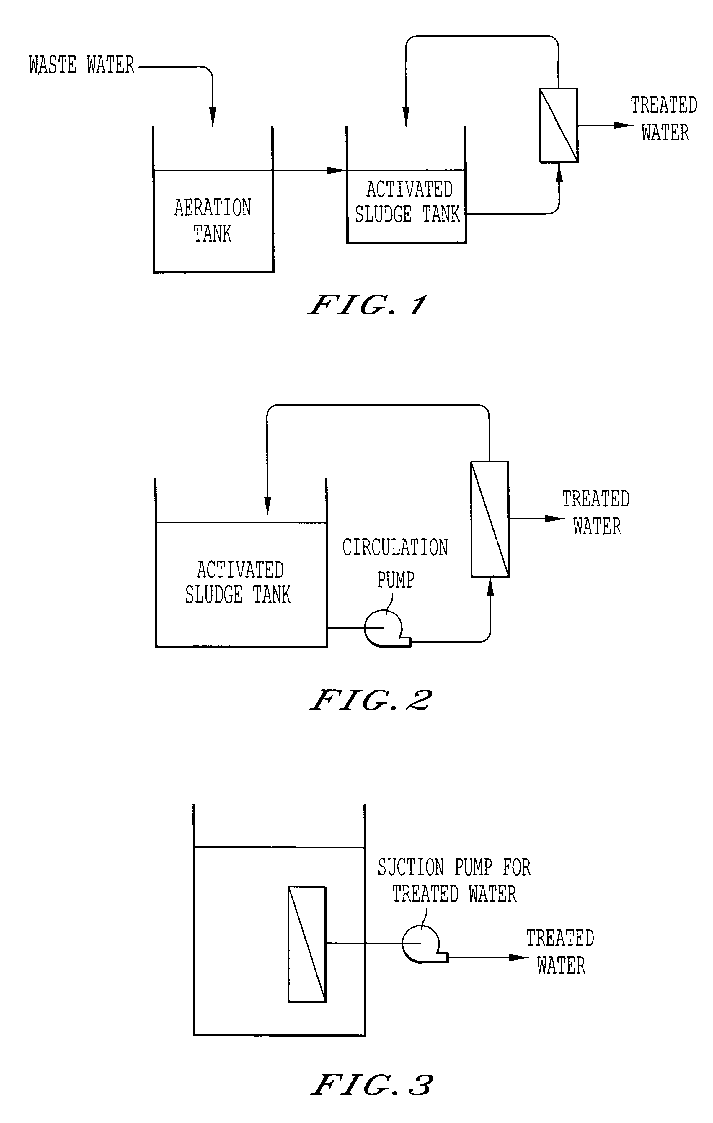
The system of FIG. 2 is advantageous in that it can be operated at a high permeation flow rate through the membrane module and that the membrane area can be reduced, but is disadvantageous in that the energy for circulating the sludge-containing waste water through the system shall be large.
On the other hand, the system of FIG. 3 is advantageous in that the disposition space and the energy for it may be small, but is disadvantageous in that the permeation flow rate through the membrane module could not be high and that the system requires a large membrane area.

Method used


Image

  • Apparatus and method for waste water treatment
  • Apparatus and method for waste water treatment

Examples


example

A pilot plant for waste water treatment was prepared for carrying out the invention, comprising a 20 m.sup.3 waste water tank, a 20 m.sup.3 carrier-fluidized aeration tank, and a 40 m.sup.3 complete oxidation tank. 2 m.sup.3 of an acetalized polyvinyl alcohol gel carrier (having a particle diameter of about 4 mm) was put into the aeration tank. A filtration membrane unit comprising two hollow fiber membrane modules of polysulfone resin (membrane area: 20 m.sup.2) was disposed outside the complete oxidation tank. Waste water was treated in this pilot plant driven in an internal-pressure circulated filtration system at a filtration rate of 20 m.sup.3 / day. With the water having passed through the separation membrane being discharged out of the complete oxidation tank, the sludge was concentrated and circulated in the system. The flowchart of the pilot plant in this Example 1 is as in FIG. 1. Based on the invention, the BOD volume load to the carrier-fluidized aeration tank was 3.5 kg / ...


PUM

PropertyMeasurementUnit
Fractionaaaaaaaaaa
Weightaaaaaaaaaa
Pore sizeaaaaaaaaaa

Abstract

Provided are an apparatus and a method for waste water treatment not generating excessive sludge, for which down-sized tanks are usable. The apparatus comprises an aeration tank where waste water to be treated is kept in contact with carrier particles in an aerobic condition, and a complete oxidation tank. In this, the liquid in the complete oxidation tank is filtered through a separation membrane and the resulting filtrate is discharged out of the system. The s-BOD sludge load to the complete oxidation tank is preferably at most 0.1 kg-BOD / kg-MLSS.day.

Description

1. Field of the InventionThe present invention relates to an apparatus and a method for waste water treatment not generating excessive sludge.2. Description of the Related ArtHeretofore, an activated sludge process has been employed generally for waste water treatment. In the process, the activated sludge is flocculated in a flocculation tank, while a part of the floc is returned to an aeration tank and the remaining part thereof, excessive sludge is drawn out of the system. With that, the process line can be constantly run under the condition of a BOD volume load falling between 0.3 and 0.8 kg / m.sup.3.day or so. On the other hand, carriers capable of carrying a high concentration of microorganisms are being developed for the process, and they enable a higher BOD volume load falling between 2 and 5 kg / m.sup.3.day applicable to the process line, and will realize down-sized aeration tanks for the process.One problem with the conventional activated sludge process is that the BOD volume...

Claims


Application Information

Patent Timeline
IPC IPC(8): B01D61/18B01D61/16C02F1/44C02F3/12C02F3/00C02F3/08
CPCB01D61/16B01D61/18C02F1/444C02F3/085C02F3/1268B01D61/145B01D2311/04C02F2003/001B01D2311/12B01D2311/2626Y02W10/10C02F3/12C02F1/44C02F3/08
Inventor BABA, YASUHIROFUJII, HIROAKISHIOTANI, TADAOOKA, KIICHIROUMIURA, TSUTOMU
Owner KURARAY CO LTD
Learn More