
Gas generator for seat belt pretensioner

Inactive Publication Date: 2002-09-24
TRW INC
View PDF23 Cites 56 Cited by
  • Summary
  • Abstract
  • Description
  • Claims
  • Application Information

AI Technical Summary

Problems solved by technology

Because the shell is plastic, it electrically isolates the propellant, but it does not hermetically seal the propellant.

Method used


Image

  • Gas generator for seat belt pretensioner
  • Gas generator for seat belt pretensioner
  • Gas generator for seat belt pretensioner

Examples


Embodiment Construction

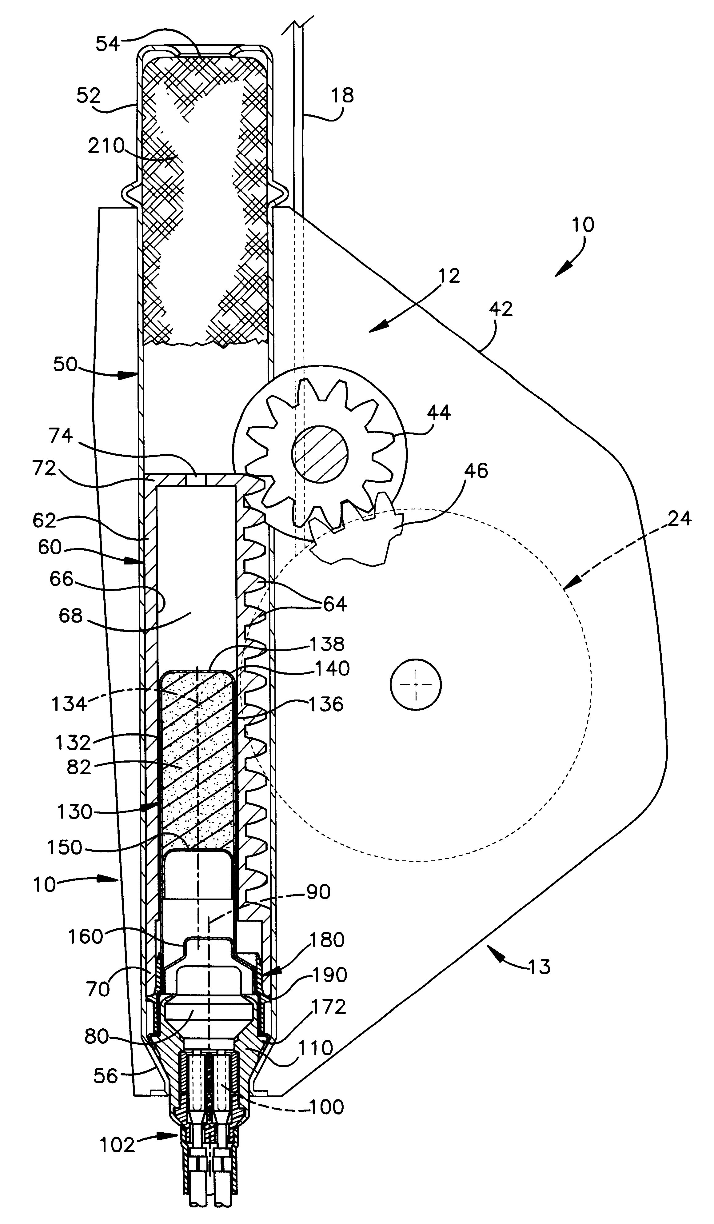
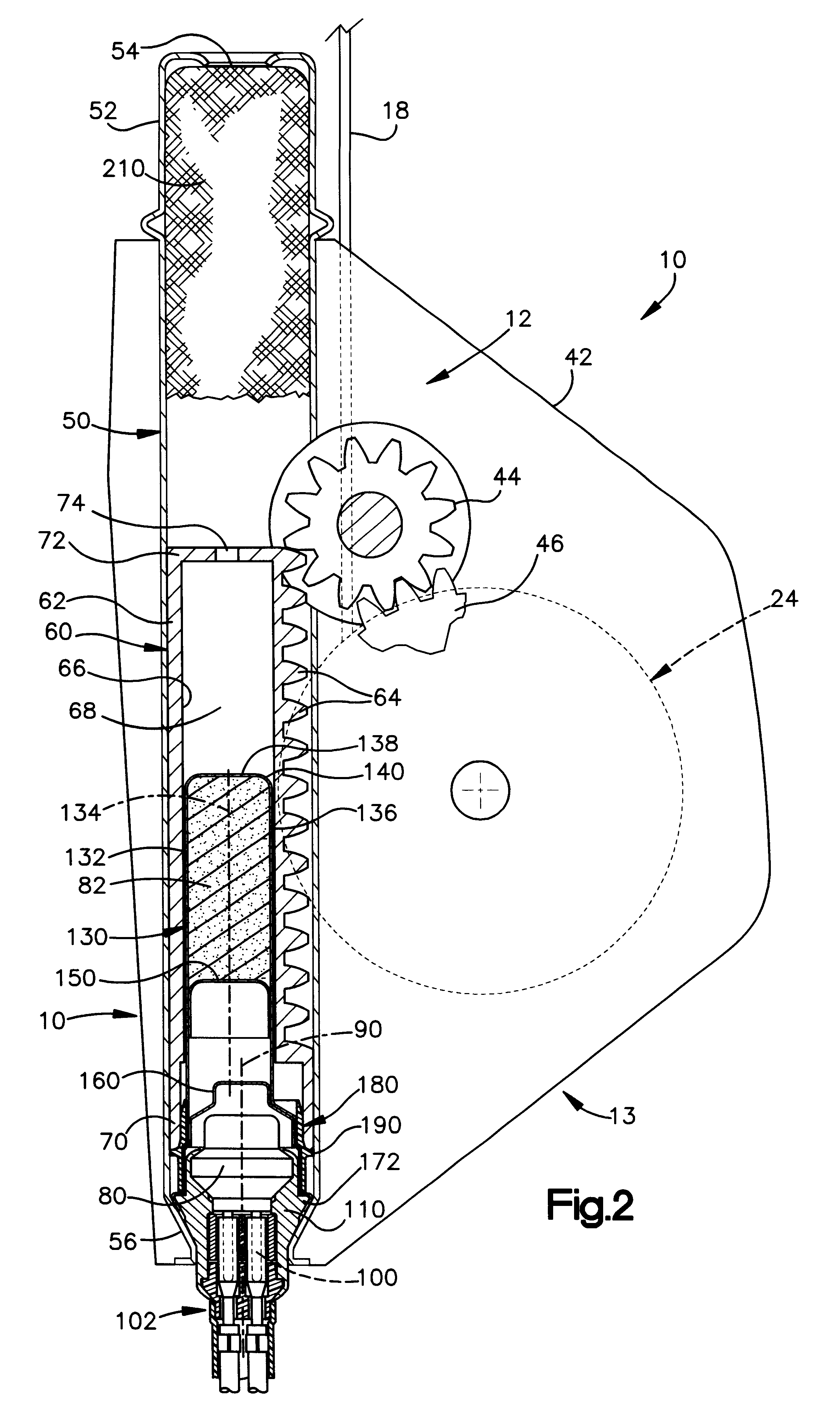
The present invention relates to an apparatus for helping to protect a vehicle occupant and, in particular, to a gas generator usable in a seat belt webbing pretensioner. As representative of the present invention, FIG. 1 illustrates a gas generator 10. The gas generator 10 is incorporated in a pretensioner 12 of a three-point continuous loop seat belt system 13 for use in restraining an occupant of a vehicle 14.

During operation of the vehicle 14, an occupant of the vehicle sits on a seat 16, which is illustrated as a front passenger seat of the vehicle. A length of belt webbing 18 is extensible about the vehicle occupant. One end of the length of belt webbing 18 is anchored to the vehicle body 20 at an anchor point 22. The opposite end of the belt webbing 18 is attached to a retractor 24 secured to the vehicle body 20. The pretensioner 12 is connected with the retractor 24. Intermediate its ends, the belt webbing 18 passes through a tongue assembly 26 and a D-ring or turning loop 2...


PUM


Abstract

An apparatus (10) for providing fluid under pressure for actuating a vehicle occupant protection device comprises an electrically actuatable initiator (80) having terminal pins (100). A hermetically sealed metal propellant container (130) contains a propellant (82) ignitable by the initiator (80) to produce fluid under pressure. The propellant container (130) is secured to the initiator (80) by crimping. The apparatus (10) also comprises a member (86) electrically insulating between the metal propellant container (130) and the terminal pins (100) of the initiator (80) to isolate the initiator electrically from the propellant container.

Description

1. Technical FieldThe present invention relates to an apparatus for helping to protect a vehicle occupant and, in particular, to a gas generator usable in a seat belt webbing pretensioner.2. Description of the Prior ArtA known vehicle seat belt system includes a retractor on which seat belt webbing is wound. The retractor has a spool, which is rotatable in a belt withdrawal direction and in an opposite belt retraction direction. The seat belt system also includes a pretensioner. The pretensioner includes a gas generator, which is electrically actuatable to produce fluid under pressure to move a piston in a cylinder. Rack teeth formed on the piston are in meshing engagement with a pinion. Upon actuation of the gas generator, fluid under pressure causes linear movement of the piston, and the rack teeth move linearly to rotate the pinion in a first direction. Rotation of the pinion in the first direction results in rotation of the seat belt webbing spool in a first direction, to remove...

Claims


Application Information

Patent Timeline
IPC IPC(8): B60R22/46B60R21/26
CPCB60R22/4633B60R2021/26029
Inventor CUNNINGHAM, CLARE R.BALL, KEITH R.SHIRK, BRYAN W.FIFIELD, JR., SHELDON R.MRAMOR, VINCENT J.PITSTICK, BRIAN R.ERIKE, ERIC C.
Owner TRW INC
Learn More