
Drive device

a technology of driving device and drive shaft, which is applied in the direction of generator/motor, piezoelectric/electrostrictive device, dynamo-electric machine, etc., can solve the problems of restricting the application field, and achieve the effect of large stroke and large for

Inactive Publication Date: 2002-09-10
FESTO AG & CO KG
View PDF6 Cites 3 Cited by
  • Summary
  • Abstract
  • Description
  • Claims
  • Application Information

AI Technical Summary

Benefits of technology

One object of the invention is to create a drive device whose characteristics are able to be varied using comparatively simple means and which in case of need renders possible performing drive movements with a large force and simultaneously a large stroke.
The drive device offers the further advantage that it may in case of need be so designed and operated that it provides for a constant drive characteristic and different stroke positions of the stroke unit may be set in a stepless manner.
Principally it would be feasible as well to design the stroke unit like a slide so that it could be displaced on the pressing faces as part of a sliding movement. In order to ensure a reliable manner of operation with minimum friction it is however preferred to utilize a stroke unit in the form of a rolling body unit, which during its drive movement rolls on the pressing faces of the pressing bodies. In order to prevent jamming in this connection the rolling body unit comprises more particularly at least two independently rotatable rolling bodies, which respectively engage only one of the pressing faces on the two pressing bodies so that the one rolling body may roll on the pressing face of the one pressing body and the other rolling body may roll on the pressing face of the other pressing body.

Problems solved by technology

While being suitable for the transmission of large forces such drives generally only perform a drive movement with relatively small force strokes.
Furthermore, there are design limitations as regards presetting the force-stroke characteristic, this restricting the field of application.

Method used


Image

  • Drive device
  • Drive device
  • Drive device

Examples


Embodiment Construction

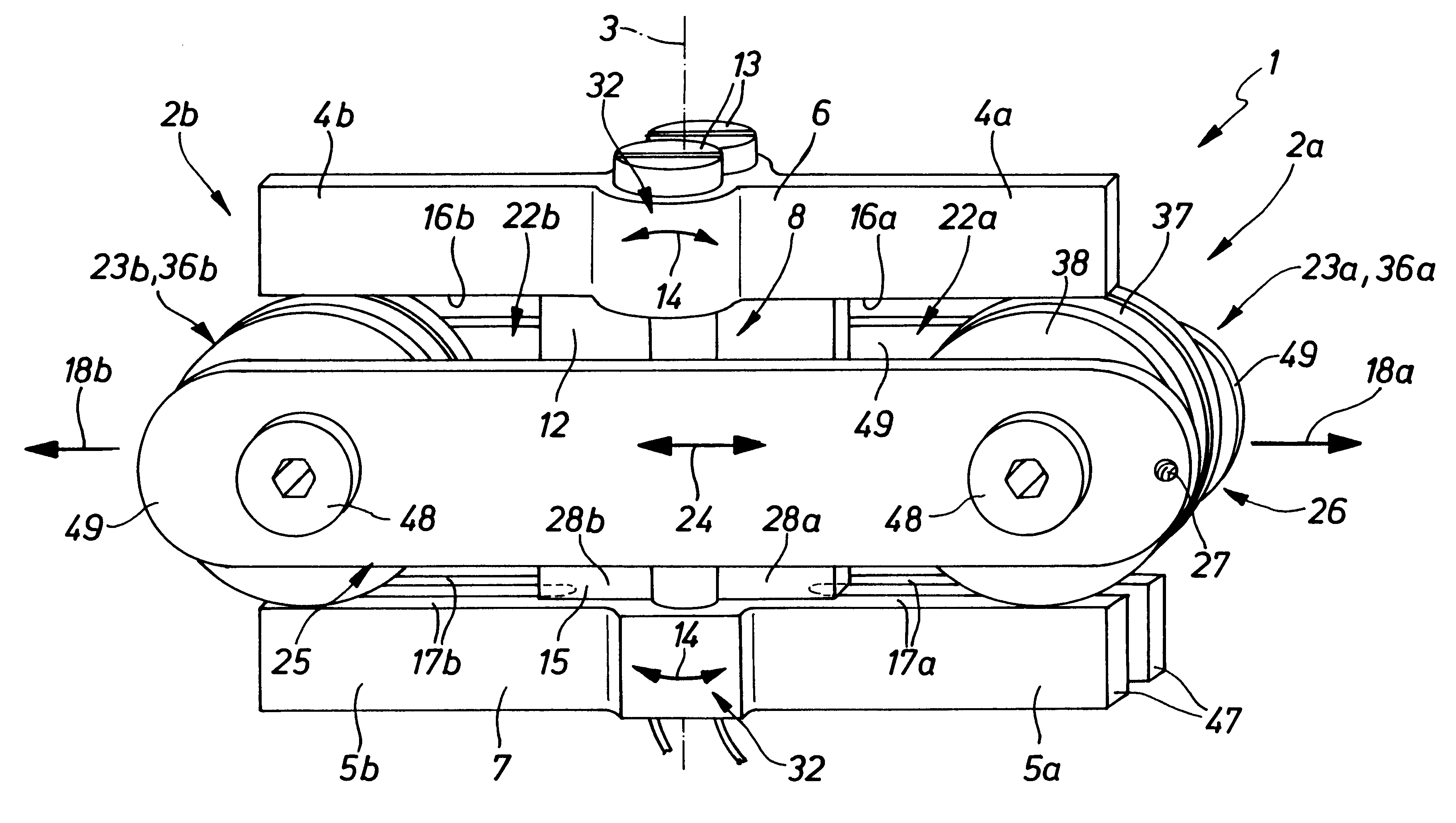
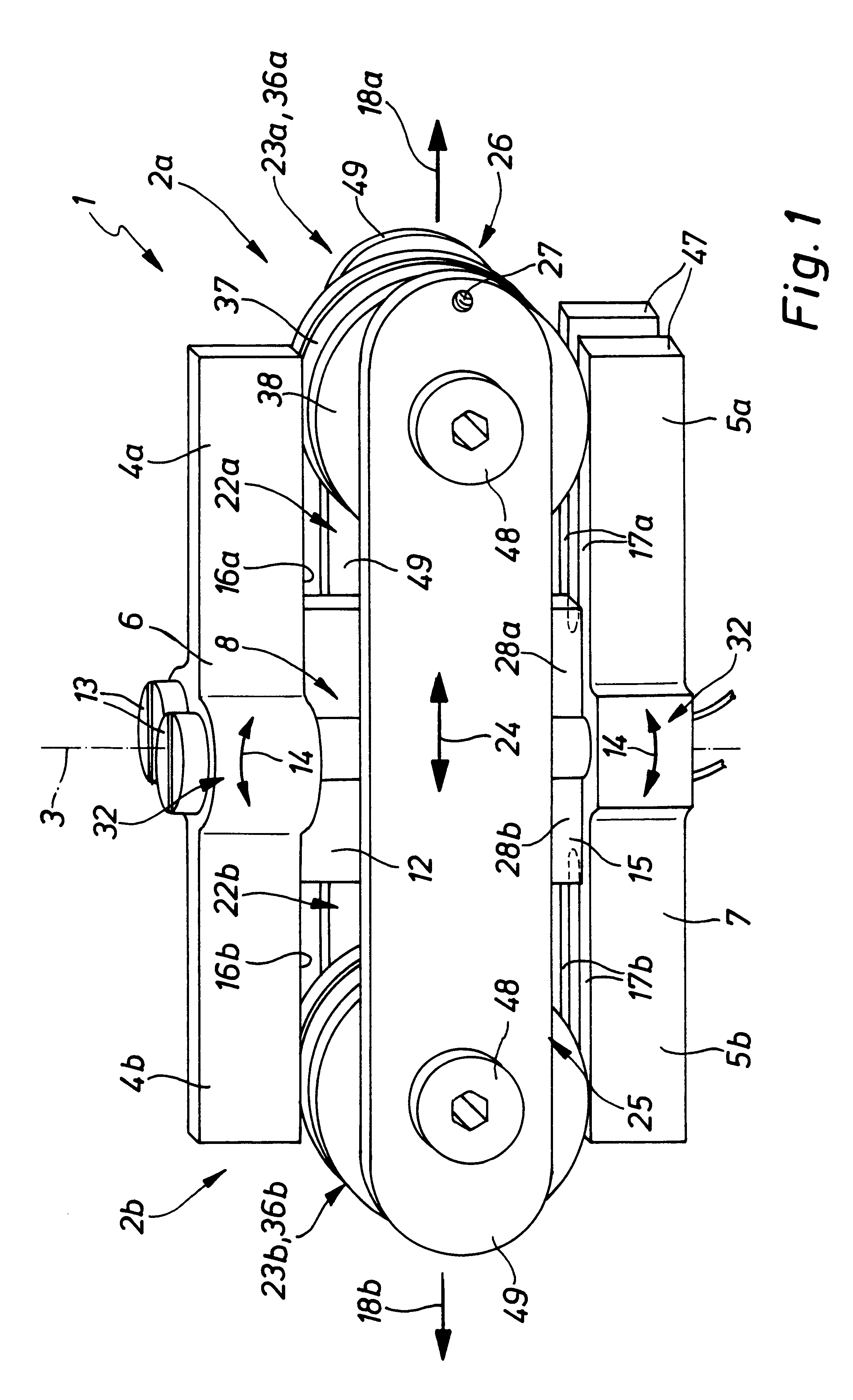
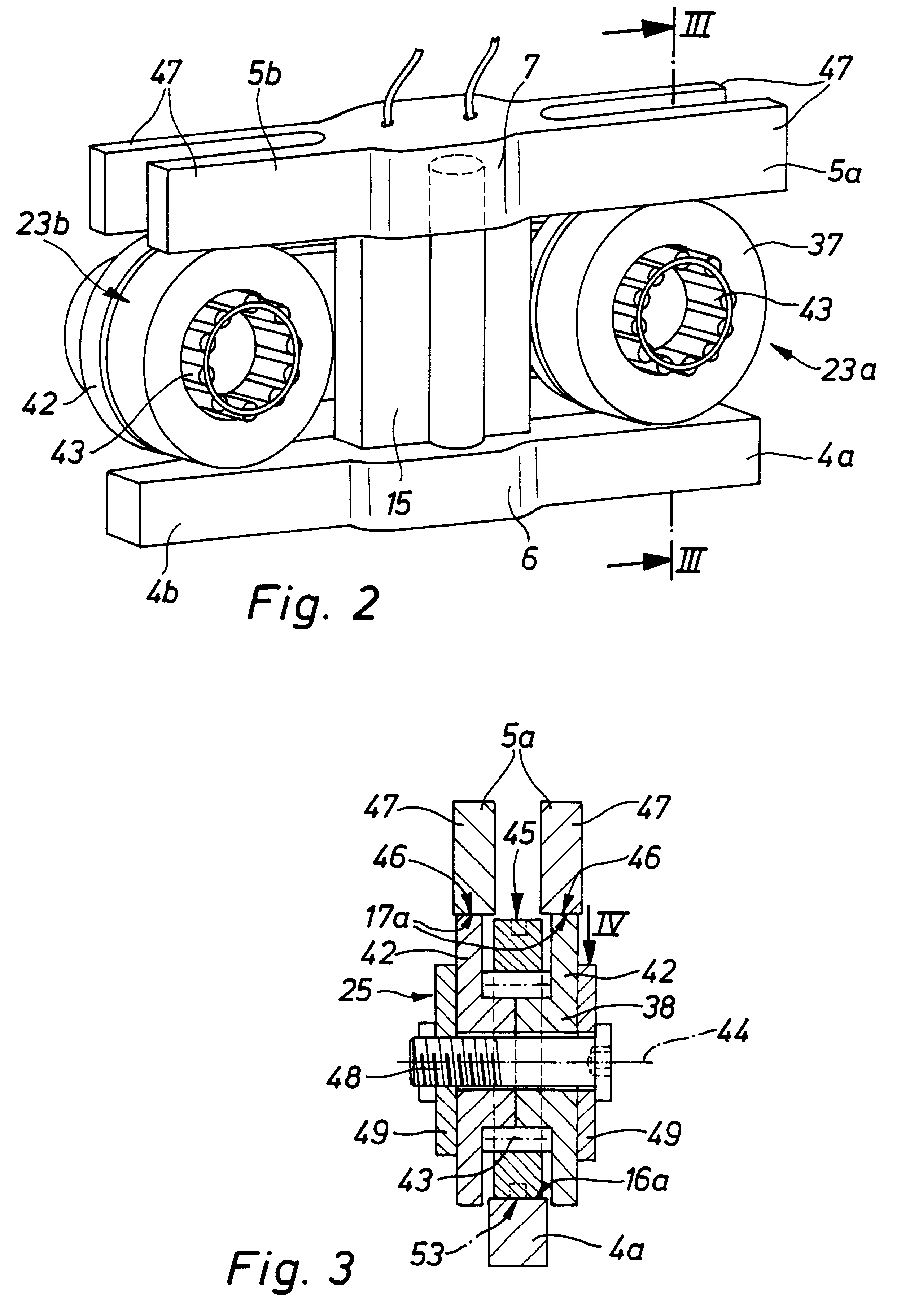
The drive device 1 illustrated in the drawings comprises two drive units 2a and 2b integrated as a single assembly, which possesses bilateral symmetry with respect to a plane containing a center axis 3.

Each drive unit 2a and 2b comprises an elongated flexurally stiff and preferably beam-like first pressing body 4a and 4b opposite which at a distance there is a second respective pressing body 5a and 5b. The first pressing bodies 4a and 4b are components of a rigid elongated first pressing element 6, and the second pressing bodies 5a and 5b are joined together as a similar second pressing element 7.

The two pressing elements 6 and 7 are pivotally mounted in a bearing zone 8 (for pivoting motion in relation to one another) in a plane containing the respective pressing elements 6 and 7. The possible pivotal movements are indicated by double arrows 14. The bearing zone is located adjacent to the center axis 3.

The two pressing elements 6 and 7 are clamped together using attachment elements...


PUM


Abstract

A drive device comprising at least one drive unit having two mutually spaced apart pressing bodies. On the pressing bodies mutual facing pressing faces are provided diverging in a drive direction and having between them a stroke unit engaging the pressing faces of both pressing bodies. Furthermore drive means are present by means of which a drawing together of the pressing bodies may be caused and, as a result of this a displacement of the stroke unit in the drive direction along the pressing faces for the purpose of producing a drive movement able to be externally employed.

Description

The invention relates to a drive device or transmission, which may for example be employed in the pneumatic equipment sector as a valve drive.THE PRIOR ARTIn connection with valves serving for the control of fluid flows in the pneumatic equipment sector so far as a rule valve drives have been utilized, which are constituted by electromagnets or piezoelectric transducers. While being suitable for the transmission of large forces such drives generally only perform a drive movement with relatively small force strokes. Furthermore, there are design limitations as regards presetting the force-stroke characteristic, this restricting the field of application.SHORT SUMMARY OF THE INVENTIONOne object of the invention is to create a drive device whose characteristics are able to be varied using comparatively simple means and which in case of need renders possible performing drive movements with a large force and simultaneously a large stroke.In order to achieve these and / or other objects appe...

Claims


Application Information

Patent Timeline
Patent Type & Authority Patents(United States)
IPC IPC(8): F16H25/18H01L41/09H10N30/20
CPCF16H25/18H02N2/043Y10T74/18568
Inventor GODEL, MARTINHOFFMANN, MARKUS
Owner FESTO AG & CO KG
Learn More