Portable electronic device for use in combination portable and fixed mount applications
- Summary
- Abstract
- Description
- Claims
- Application Information
AI Technical Summary
Benefits of technology
Problems solved by technology
Method used
Image

Examples
Embodiment Construction
.
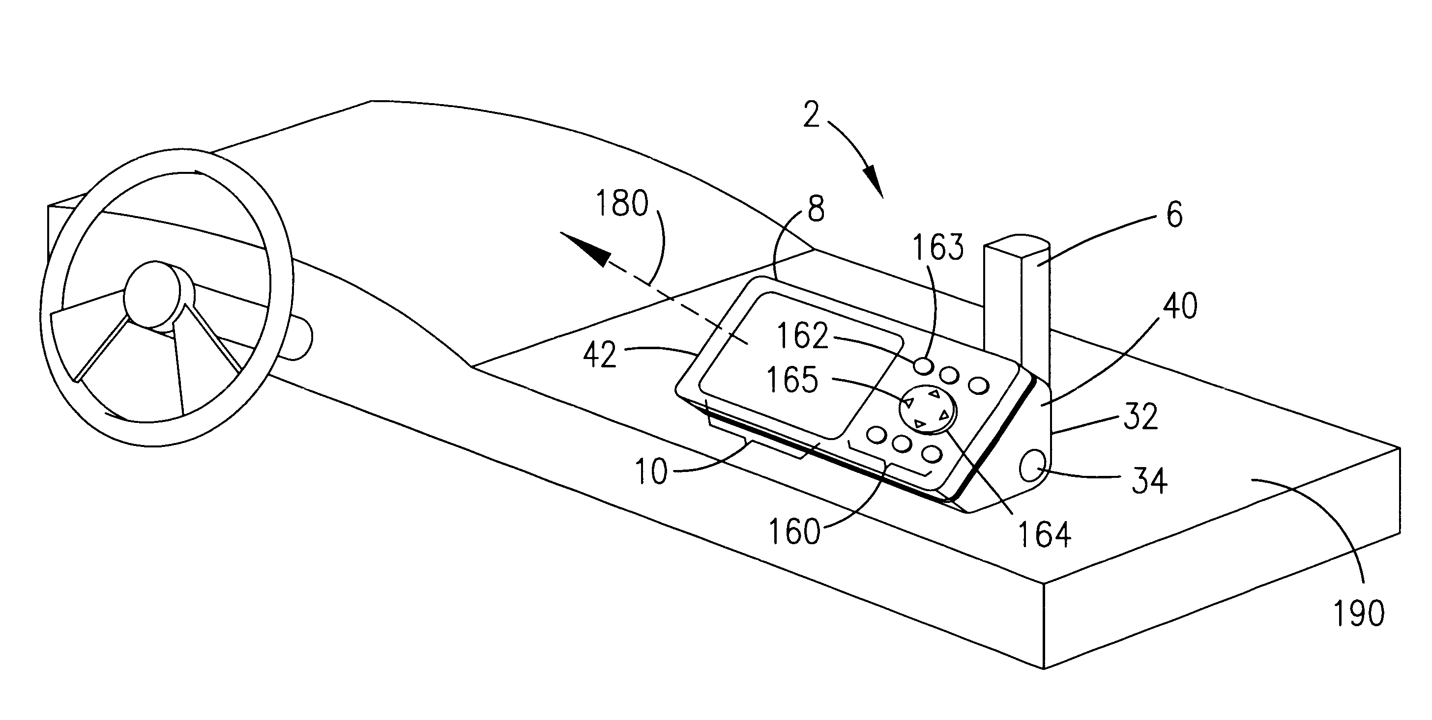
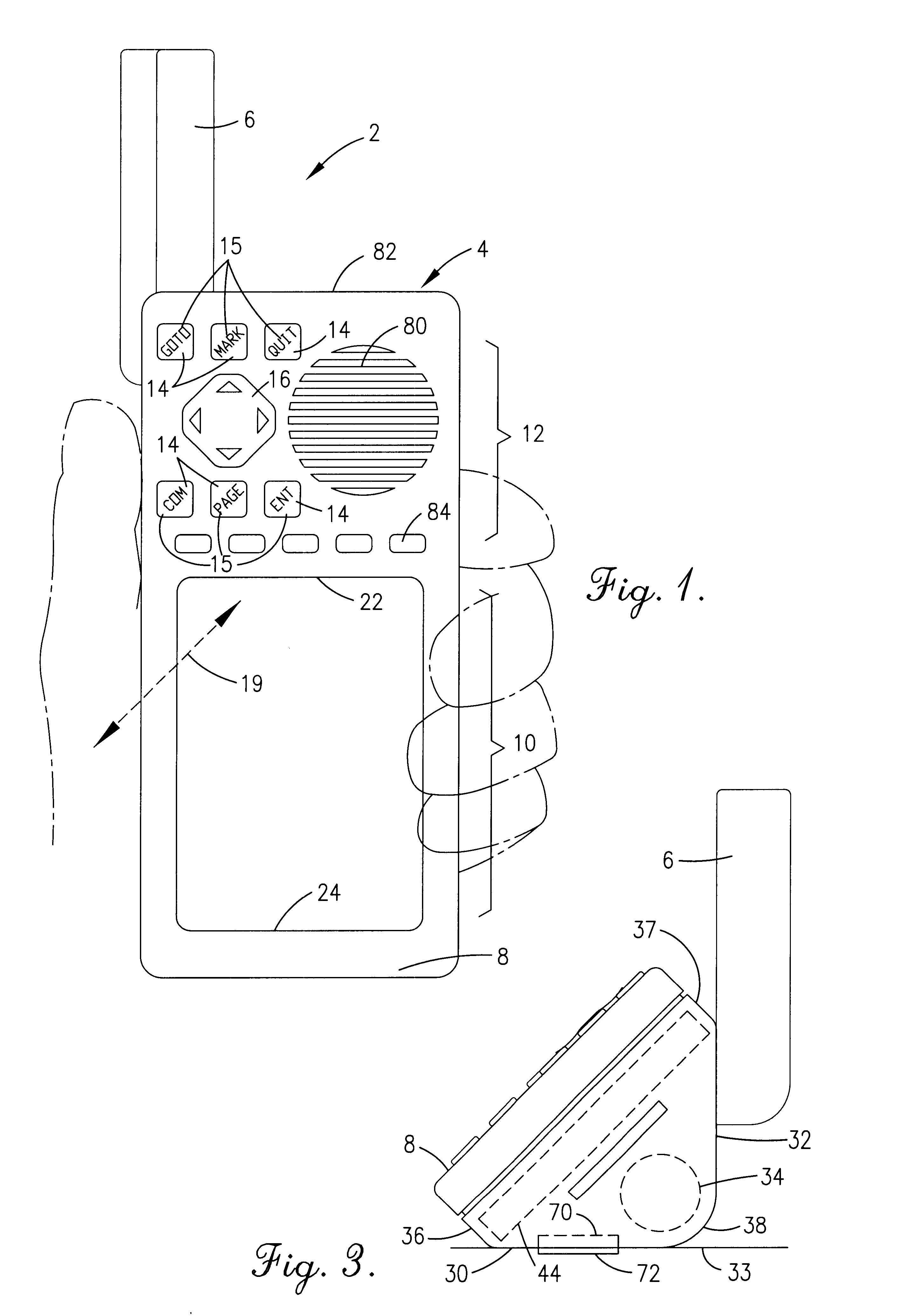
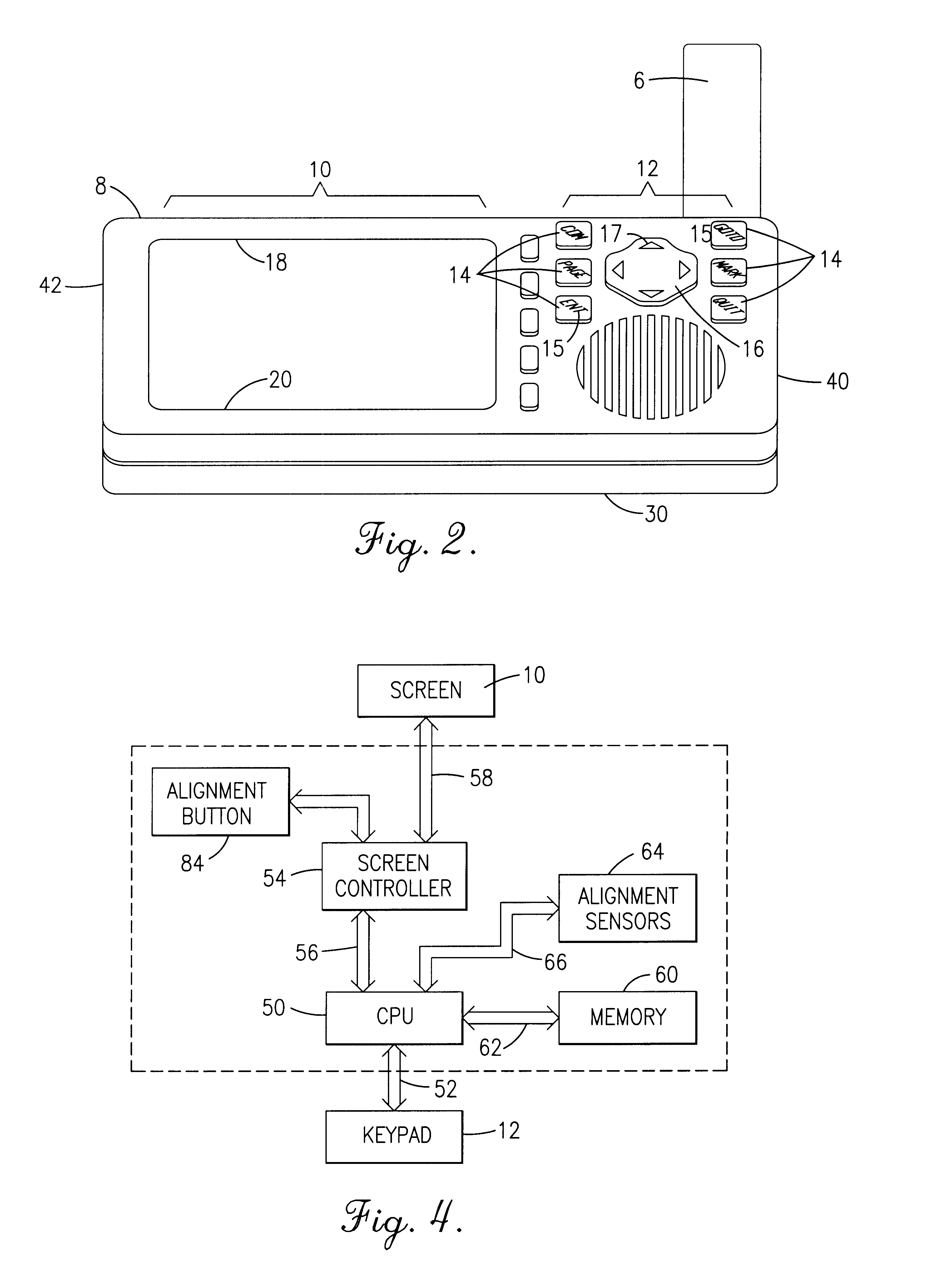
FIG. 1 illustrates a portable electronic device (generally designated by the reference numeral 2) according to the present invention. The electronic device 2 of FIG. 1 is oriented along a vertical axis, such as when held by a user. The portable device 2 includes a polyhedron-shaped housing 4 having a face plate 8, a base 30, and a back wall 32 generally forming a right triangular cross-section (as illustrated in FIG. 3). The base 30 and back wall 32 are formed generally at right angles to one another with the face plate 8 forming the hypotenuse of the triangle. The device 2 further includes an antenna 6 rotatably mounted at one corner of the housing 4 to the back wall 32. The antenna 6 is rotatable about 360.degree. between a plurality of discrete positions, two of which are illustrated in FIGS. 1 and 2. As illustrated in FIG. 1, the antenna 6 may be positioned to extend substantially parallel to the longitudinal axis of the housing 4 during a hand-held application. As illustrated ...
PUM
 Abstract
Description
Claims
Application Information
 - R&D
- Intellectual Property
- Life Sciences
- Materials
- Tech Scout
- Unparalleled Data Quality
- Higher Quality Content
- 60% Fewer Hallucinations
Browse by: Latest US Patents, China's latest patents, Technical Efficacy Thesaurus, Application Domain, Technology Topic, Popular Technical Reports.
© 2025 PatSnap. All rights reserved.Legal|Privacy policy|Modern Slavery Act Transparency Statement|Sitemap|About US| Contact US: help@patsnap.com