
Equalization system using general purpose filter architecture

a filter architecture and general purpose technology, applied in the field of equalization systems, can solve the problems of large heat generation of receivers, and large power consumption of receivers

Inactive Publication Date: 2002-06-25
RAYTHEON CO
View PDF1 Cites 141 Cited by
  • Summary
  • Abstract
  • Description
  • Claims
  • Application Information

AI Technical Summary

Problems solved by technology

Unfortunately, digital radar receivers implemented in accordance with conventional teachings often require several hundred signal processing chips.
As a result, conventional digital radar receivers are typically heavy, bulky, and expensive to develop and manufacture.
In addition, these receivers typically consume considerable power and generate much heat.

Method used


Image

  • Equalization system using general purpose filter architecture
  • Equalization system using general purpose filter architecture
  • Equalization system using general purpose filter architecture

Examples


Embodiment Construction

Illustrative embodiments and exemplary applications will now be described with reference to the accompanying drawings to disclose the advantageous teachings of the present invention.

While the present invention is described herein with reference to illustrative embodiments for particular applications, it should be understood that the invention is not limited thereto. Those having ordinary skill in the art and access to the teachings provided herein will recognize additional modifications, applications, and embodiments within the scope thereof and additional fields in which the present invention would be of significant utility.

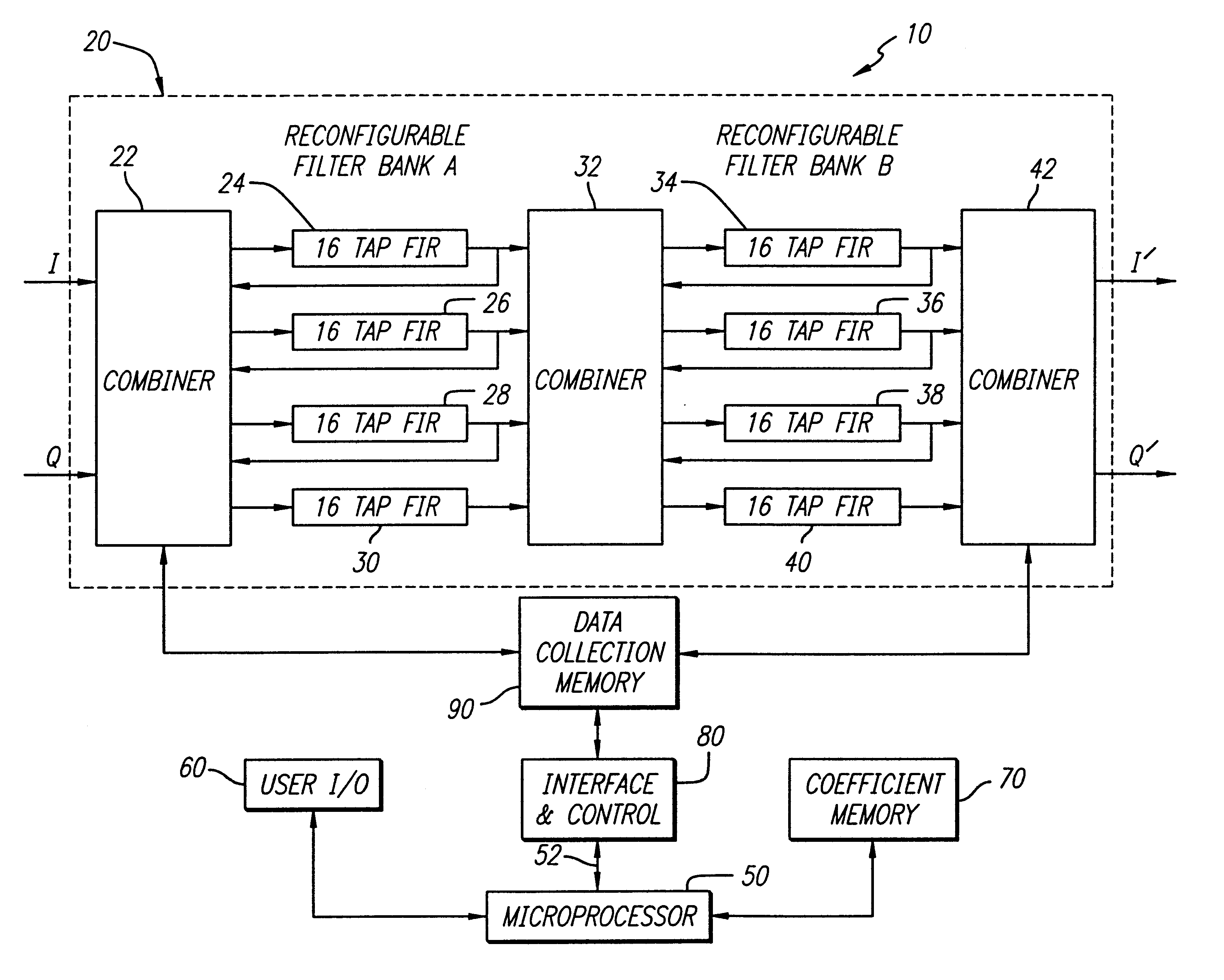
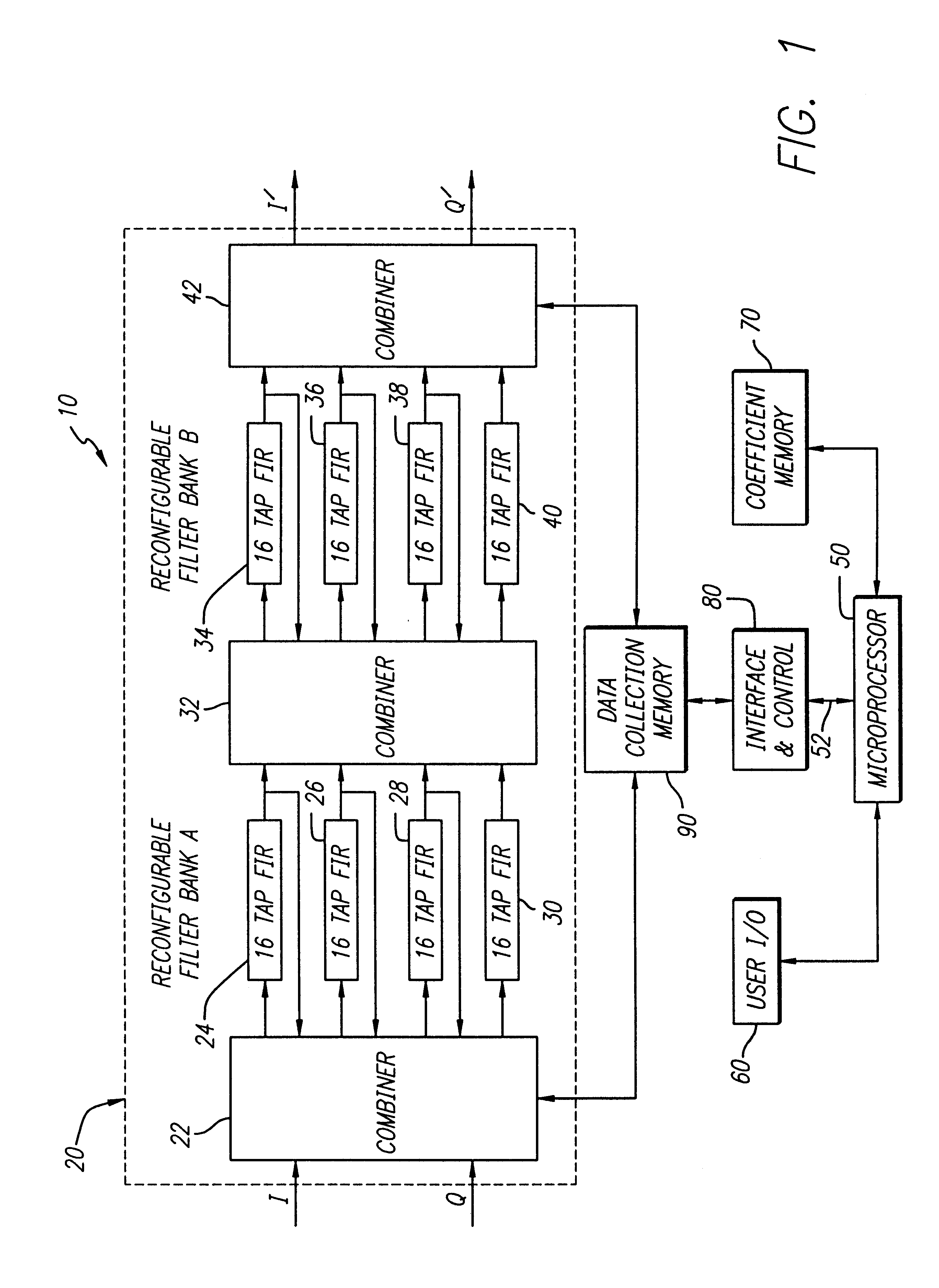
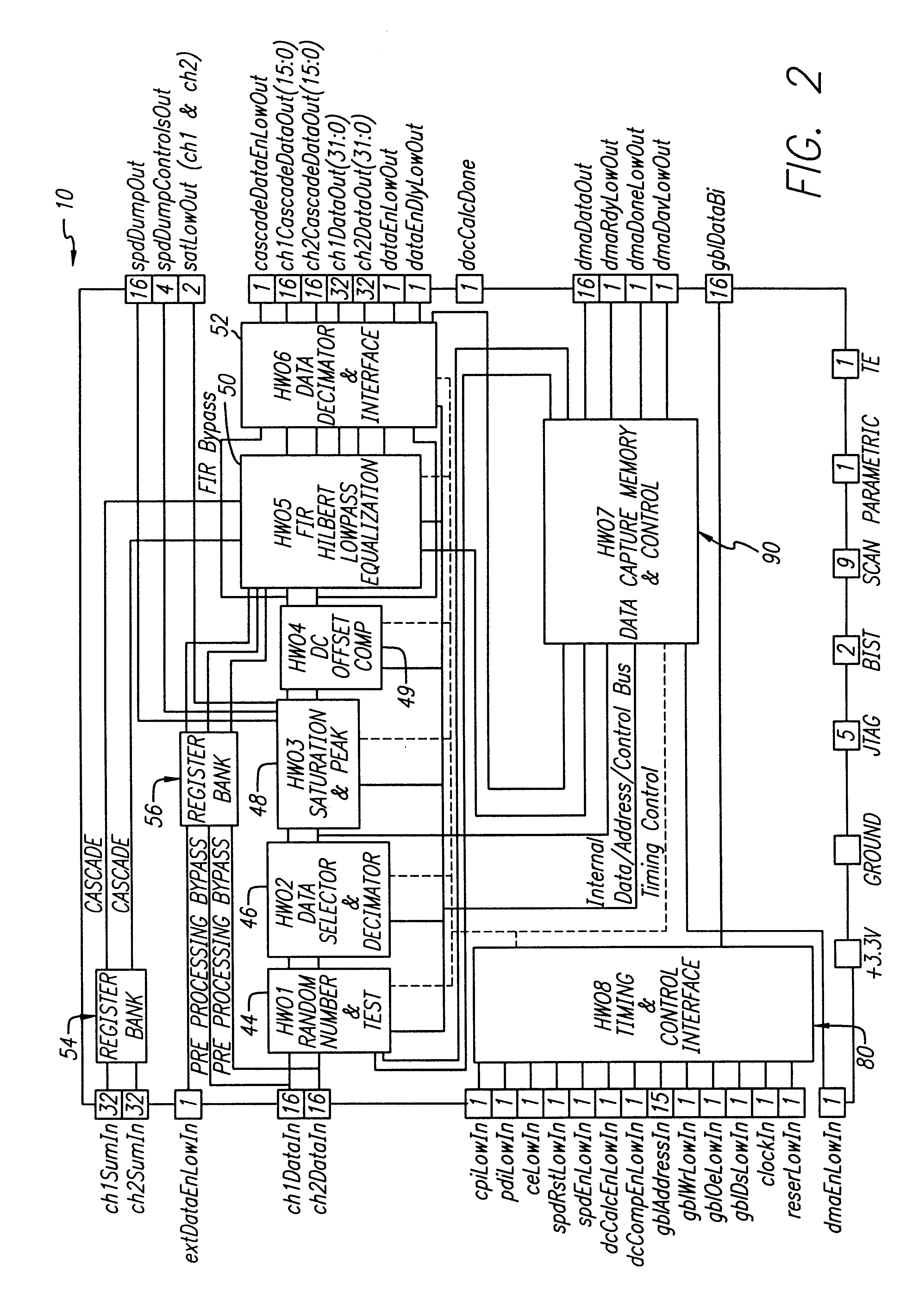
FIG. 1 is a block diagram of a general purpose filter constructed in accordance with the teachings of the above-referenced and incorporated application filed by Cox et al. along with associated control circuitry. The system 10 consists of the general purpose filter 20, a microprocessor 50, a user interface 60, a coefficient memory 70, an interface and control ci...


PUM


Abstract

An equalization system and method. In a most general sense, the inventive equalization system includes first and second filters for filtering an in-phase component of a received signal in accordance with first and second sets of coefficients, respectively. The system includes third and fourth filters for filtering a quadrature component of the input signal in accordance with third and fourth sets of coefficients, respectively. The outputs of the first and third filters are subtracted to provide an equalized in-phase output signal and the outputs of the second and fourth filters are added to provide an equalized quadrature output signal. In the illustrative embodiment the filters are finite impulse response filters and the coefficients are provided by a microprocessor. In accordance with the present teachings, the filters are implemented in a general purpose filter. The delay elements of the filters are calculated in accordance with a mean square error algorithm. Accordingly, the coefficients are the product of the correlation between inputs to the delay elements and a cross correlation between the inputs and a set of values representative of a desired response.

Description

A portion of the disclosure of this Patent document contains material which is subject to copyright protection. The copyright owner has no objection to a facsimile reproduction, by any one, of the patent document or the patent disclosure, as it appears in the Patent and Trademark Office patent files or records, but otherwise reserves all copyrights with respect thereto.1. Field of the InventionThe present invention relates to radar receivers. More specifically, the present invention relates to equalization systems used in high performance digital radar receivers.2. Description of the Related ArtSophisticated high performance military and commercial digital radar receivers detect and process signals in complicated environments that include broadband clutter, interference sources (intentional and unintentional), echoes, and receiver noise. These receivers perform some or all of the following functions: synthesis of in-phase (I) and quadrature (Q) components from high-speed sampled sig...

Claims


Application Information

Patent Timeline
IPC IPC(8): G01S7/285H03H17/02H04N5/14
CPCG01S7/285H04N5/14H03H17/0294
Inventor COX, LLOYD C.GRAMLICH, GARY A.BAKER, ROBERT M.FREEMAN, STEPHENNEARY, BRIAN P.KRZEMIEN, CYNTHIA R.KRIM, JORDAN A.NUNEZ, LUIS R.
Owner RAYTHEON CO
Learn More