
Memory disc, manufacturing method thereof, and method of manufacturing disc drive utilizing such memory disc

Inactive Publication Date: 2002-06-25
SHOWA DENKO KK
View PDF14 Cites 62 Cited by
  • Summary
  • Abstract
  • Description
  • Claims
  • Application Information

AI Technical Summary

Benefits of technology

It is a still another object of the invention to provide a memory disc which is less wearable.
It is a further object of the invention to provide a memory disc which may reduce wear of a head slider in a memory disc device.
It should be noted that as mentioned above the invention utilizes a non-fluid bonding layer as a lubricant layer on the memory disc for facilitating reduction of the friction between the head slider of a head and the memory disc during read / write operations by the head while it is in rotational motion over the disc, thereby reducing the wear of the lubricant layer caused by the friction.
With a thicker lubricant layer in the CSS region than in the data region, friction between the lubricant layer and the head slider is greatly reduced in the CGS region, so that the lubricant layer will become durable over extended periods of time.

Problems solved by technology

However, if the roughness is too small, a net contact area between the magnetic head and the magnetic disc will become too large, which often causes the magnetic head to adhere or stick to the magnetic disc and causes it to fail to float.
These protrusions, however, will result in a large pressure on the small contact area of each protrusion, and therefore it is likely that the lubricant layer in the contact area will be easily worn out if the lubricant layer is very thin.
Lack of the lubricant layer in the contact area will result in solid-solid contact between the magnetic head and the disc, causing impermissible friction between them.
It is often the case that protrusions are also worn out quickly under such condition.
However, he has found that a thick layer of conventional lubricant on the disc cannot reduce the friction between them, due to the fact that the lubricant eventually gets moved radially outward by centrifugal forces acting on it while spinning the disc.
Thus, the NiP layer is prepared by adding P to Ni in the non-electric plating process, to thereby making a resultant NiP anomalous.

Method used


Image

  • Memory disc, manufacturing method thereof, and method of manufacturing disc drive utilizing such memory disc
  • Memory disc, manufacturing method thereof, and method of manufacturing disc drive utilizing such memory disc
  • Memory disc, manufacturing method thereof, and method of manufacturing disc drive utilizing such memory disc

Examples


second example

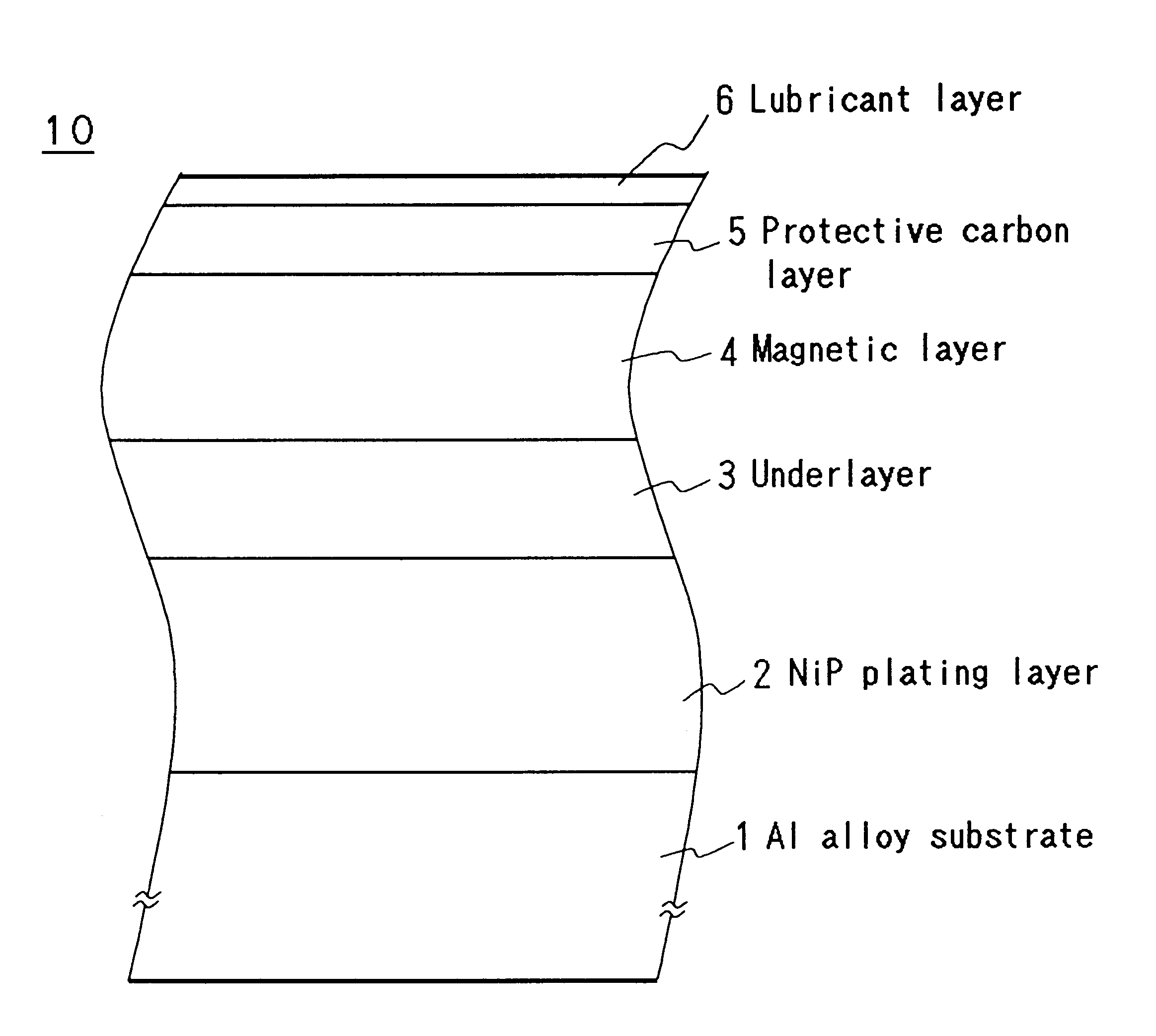
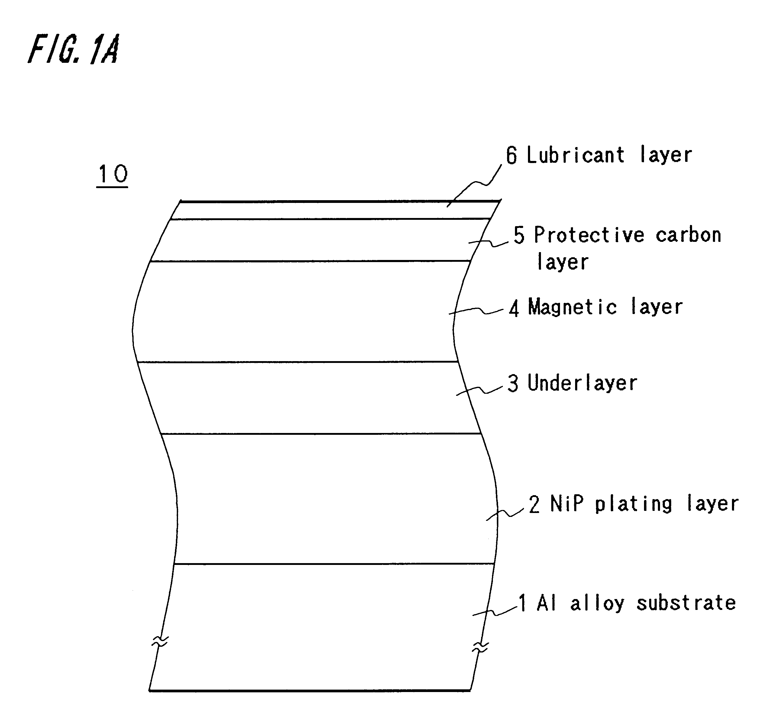
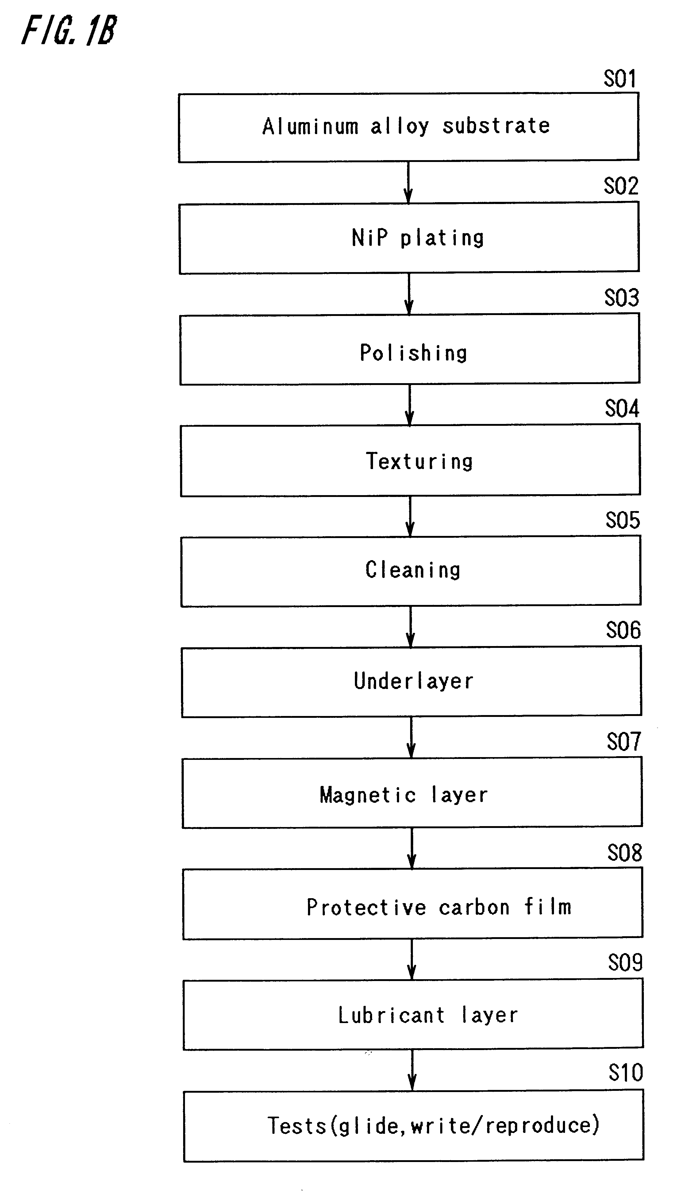
FIG. 3 shows details of step S09 of FIG. 1B, illustrating a second procedure for forming a lubricant layer 6 on the magnetic disc substrate. At this stage the magnetic disc substrate has completed the steps up to step S08 and has a protective carbon layer thereon.

As shown in FIG. 3A, the magnetic disc substrate 10 is coated with a fairly thick fluoride lubricant layer, the thickness of which is about 2.0 nm in the example shown herein. The same lubricant, solvent, coating method, and coating conditions as for the first example discussed in connection with FIG. 2A may be used equally well in this example.

After the magnetic disc substrate 10 is coated with the lubricant 6, the substrate 10 is subjected to a two-stage adhesion treatment as shown in FIG. 3B and described in detail below. It is noted that this adhesion treatment is different from one used in the first example.

(1) In the first stage of the treatment, it is applied only to the lubricant within the CSS region of the magneti...


PUM


Abstract

A memory disc for use in a memory disc, comprising a lubricant layer which consists essentially of a non-fluid bonding lubricant, or comprises a lubricant layer which contains at least 90% of non-fluid bonding lubricant. Such memory disc is fabricated through steps of: forming a protective carbon layer; coating a lubricant on a disc substrate; subjecting the resultant substrate to an adhesion treatment to form a bonding layer of lubricant adhering to the disc substrate; and removing a free fluid layer of the lubricant remaining on the bonding layer. Thus, the memory disc has essentially no fluid component that can flow during read / write operations.

Description

1. Field of the InventionThe invention generally relates to a memory disc for use in a memory disc device such as magnetic disc drives and optical disc drives, and more particularly to a memory disc having thereon a lubricant layer.2. Description of the Prior ArtHard disk drives (HDD) have been commonly used as auxiliary memory devices for personal computers and engineering work stations to store a large amount of information. A HDD uses a magnetic disk to read / write information on the disc. In order to deal with ever increasing information, efforts have been made to improve their capacity for a higher recording density as well as their down sizing. For example, up until 1991, the recording density on a magnetic disk was increased at the rate of about 10 times per 10 years. It was then prospected that the recording density would be 10.sup.3 Mega bytes (MB) / in.sup.2 (1 Gb / in.sup.2) by the year of 2000.However, in actuality the recording density has increased much faster than the pros...

Claims


Application Information

Patent Timeline
IPC IPC(8): G11B5/72G11B23/00G11B5/64G11B5/82G11B5/725G11B5/60G11B5/71G11B5/73G11B5/84
CPCG11B5/64G11B23/0021G11B5/82G11B5/725G11B5/6011G11B5/7257G11B5/71
Inventor KASAMATSU, YOSHIHARUTOYOGUCHI, TAKASHIYAMAMOTO, TAKAYUKI
Owner SHOWA DENKO KK
Learn More