
Golf ball with non-circular shaped dimples

a golf ball and non-circular technology, applied in the field of golf balls with non-circular shaped dimples, can solve the problems of ineffective maximization of fixed turbulence creating space, and ineffective maximization of dimple surface area on the ball

Inactive Publication Date: 2002-06-25
THE PROCTER & GAMBLE COMPANY
View PDF39 Cites 203 Cited by
  • Summary
  • Abstract
  • Description
  • Claims
  • Application Information

AI Technical Summary

Problems solved by technology

Smaller dimples have been found to be not as effective in creating turbulence as larger dimples, and larger size dimples ineffectively maximize the fixed turbulence creating space (i.e. the surface of the golf ball).
Similarly, substantially uniform land portions between dimples may also be desirable because too thin a land portion may create manufacturing problems and too large a land portion may ineffectively maximize the surface area of dimples on the ball.
Moreover, large variations in dimple size or land portions may negatively affect the aerodynamic properties of the ball.
In other words, the alignment of the sides of any three dimples on a golf ball reduces the air turbulence created in front of the ball, which results in increased drag when the ball is in flight.
A typical drawback with the dimples in these examples is that the dimple patterns do not meet the spherical symmetry standard as required by The United States Golf Association (U.S.G.A.).

Method used


Image

  • Golf ball with non-circular shaped dimples
  • Golf ball with non-circular shaped dimples
  • Golf ball with non-circular shaped dimples

Examples


Embodiment Construction

Reference will now be made in detail to various exemplary embodiments of the invention, several of which are also illustrated in the accompanying drawings, wherein like numerals indicate the same element throughout the views.

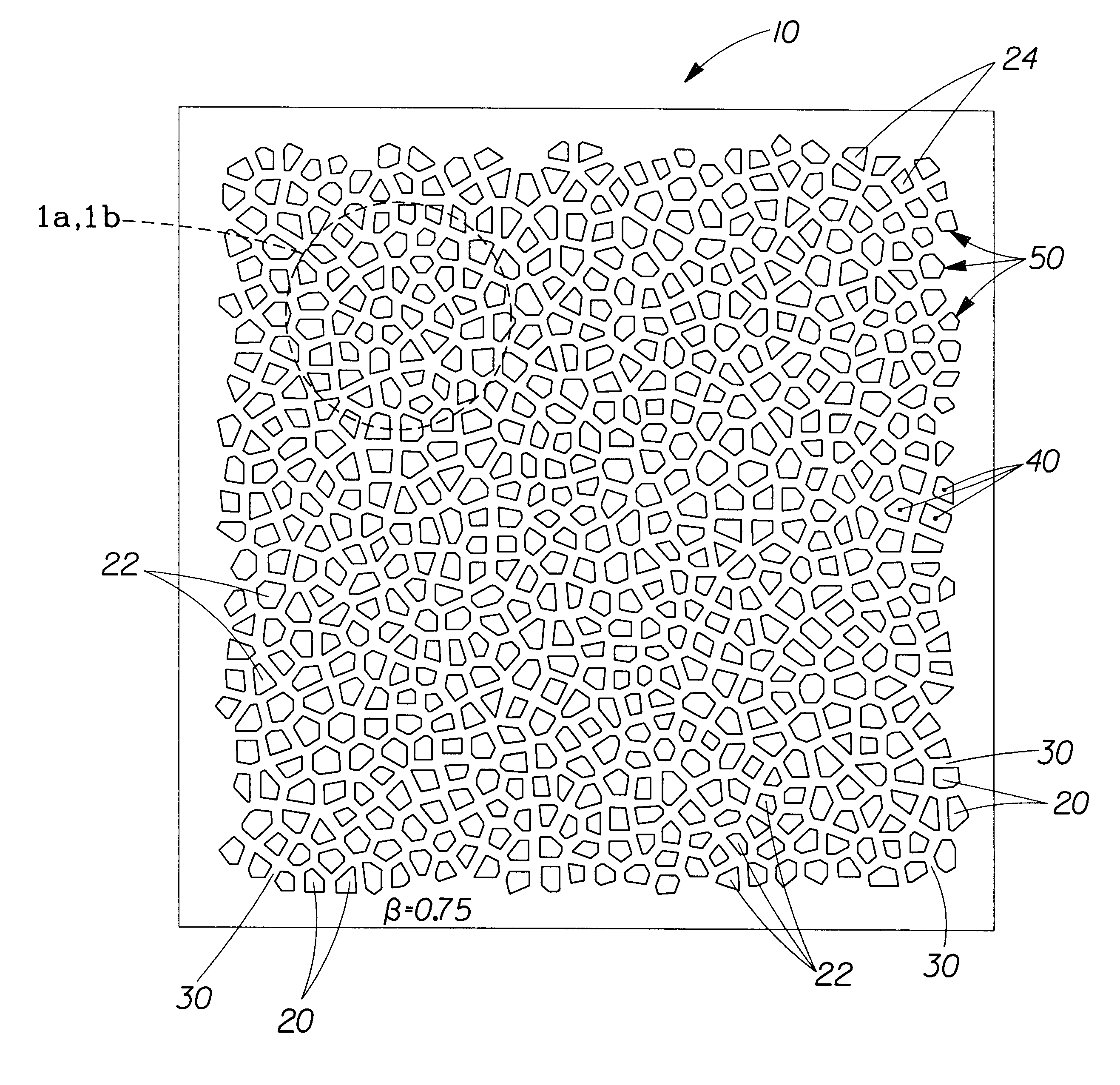
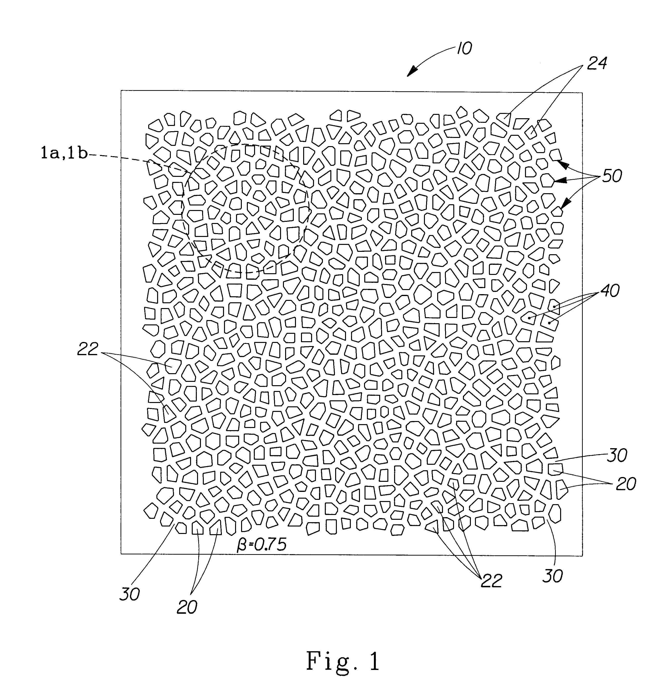
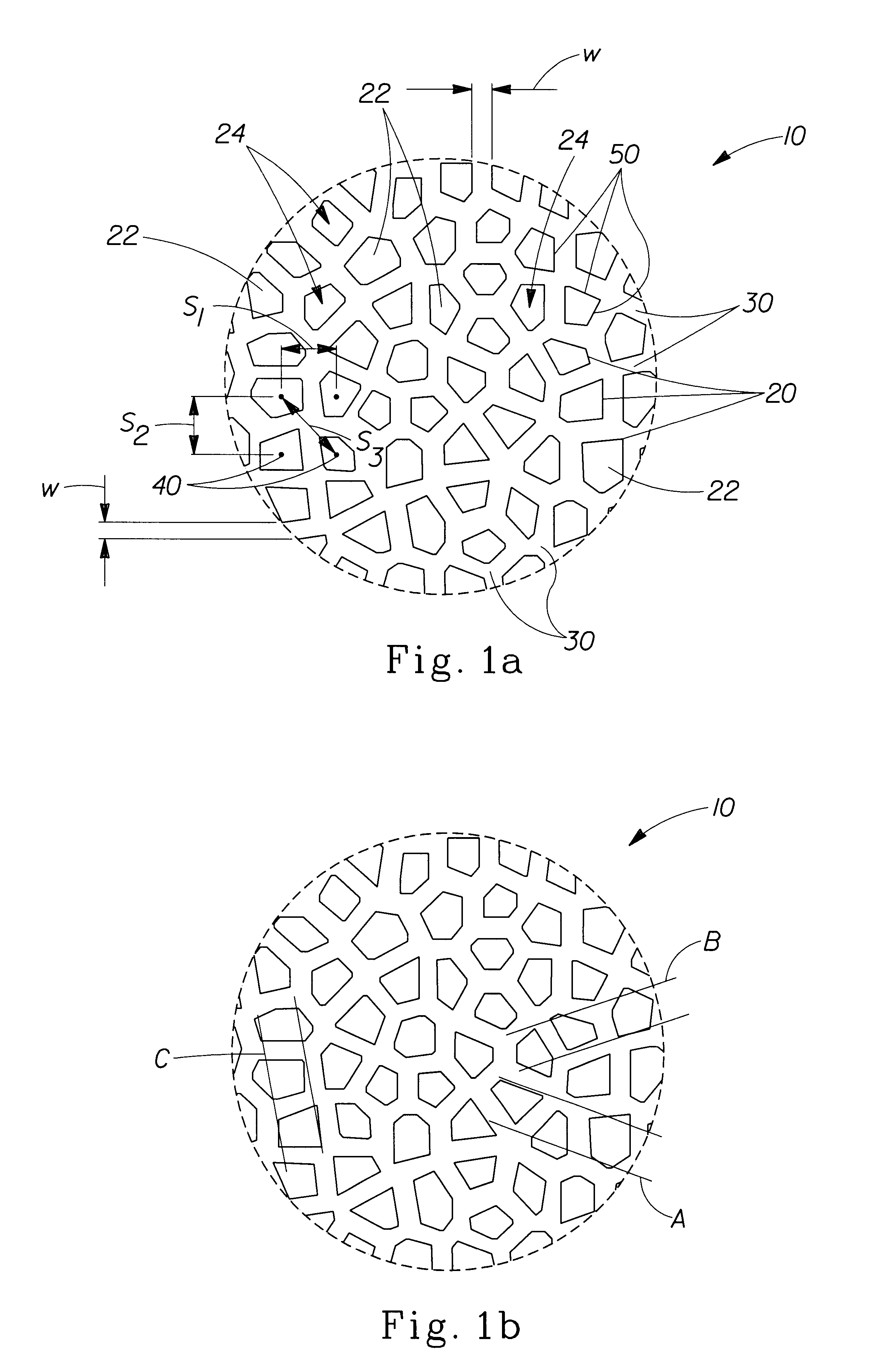
FIG. 1 and 1a, an exploded view of FIG. 1, depict a specific embodiment of an exemplary golf ball dimple pattern 10 in accordance with the present invention. The dimple pattern 10 comprises dimples 20 in the surface of a golf ball separated by interposed land portions 30, which defines the width "w" between adjacent dimples 20. As will be observed, in an amorphous dimple pattern, the arrangement and shape of one dimple 20 with regard to a neighboring dimple 20 is random. In other words, the arrangement and shape of one dimple 20 with regard to a neighboring dimple 20 bears no predictable relationship to that of adjacent or succeeding dimple(s) beyond. In addition, the orientation, size, spacing and / or other characteristics of one dimple 20 with regard to a neigh...


PUM


Abstract

In a non-limiting exemplary embodiment of the present invention, a golf ball has a surface comprising a plurality of dimples arranged in an amorphous pattern. In an additional embodiment of the invention, a golf ball has a surface comprising a plurality of spaced dimples, wherein the dimples each comprise a non-circular shape and are spaced by land portions having substantially uniform widths. In an additional embodiment of the present invention, a golf ball has a surface formed with a plurality of non-circular, multi-sided shaped dimples and interposed lands having substantially consistent widths between adjacent dimples. In yet another alternative embodiment of the present invention, an exemplary method of making a golf ball having a dimpled surface is provided. The process comprises generating an amorphous pattern of non-circular shaped dimples and then transferring the amorphous pattern to the surface of the golf ball.

Description

The present invention relates to a golf ball with an improved amorphous pattern of non-circular shaped dimples that provides enhanced performance. A method for generating such a dimple pattern using a constrained Voronoi tessellation on the surface of a ball is also presented.BACKGROUND OF INVENTIONDimples are provided in the surface of a golf ball to improve the aerodynamic characteristics and flight distance of the ball. The primary purpose for employing dimples is to reduce the in flight drag on the golf ball, thereby increasing the distance the golf ball can travel. In particular, drag is the air resistance that acts on the golf ball in an opposite direction to the ball's flight. Essentially, as the ball travels through the air, the dimples create turbulence in front of the ball, which reduces the pressure differential between the front and the rear of the ball. As a result, a high degree of dimple coverage is desirable due to the increased turbulence created, which consequently...

Claims


Application Information

Patent Timeline
Patent Type & Authority Patents(United States)
IPC IPC(8): A63B37/00A63B45/00
CPCA63B37/0004A63B37/0006G06T17/20A63B37/0009A63B37/002A63B37/0007A63B37/14
Inventor MCGUIRE, KENNETH STEPHENTWEDDELL, III, RICHARDHAMILTON, PETER WORTHINGTON
Owner THE PROCTER & GAMBLE COMPANY
Learn More