
Device and method for measuring hay bale moisture

a technology for moisture measurement and bales, applied in the direction of instruments, agriculture tools and machines, weighing by absorbing components, etc., can solve the problems of significant effected accuracy, affecting accuracy, and inability to test prior art sensors,

Inactive Publication Date: 2002-04-23
HARVEST TEC
View PDF22 Cites 33 Cited by
  • Summary
  • Abstract
  • Description
  • Claims
  • Application Information

AI Technical Summary

Benefits of technology

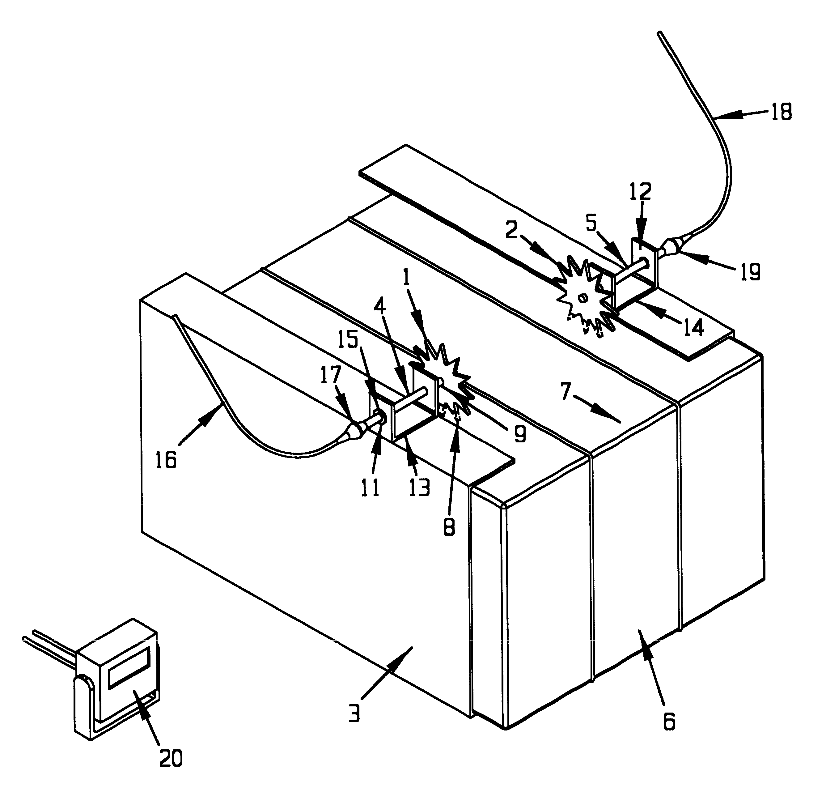
The present invention is a device with two star-shaped wheels that are mounted on a hay baler. These wheels have points that rotate into the hay being baled, and these points are driven by the moving hay. The device also includes an electrically isolated arrangement to prevent short circuits between the wheels and the baler. Additionally, the device has means to transmit direct current voltage to the wheels and means to receive the voltage through the hay. The received voltage is then scaled and displayed on a readout box. The readout box can also control other processes or provide alternative signals. The technical effect of this invention is to provide a device that can measure moisture in real-time during the baling process, which can help improve the quality and efficiency of the baling process.

Problems solved by technology

The technical problem of this patent text is not specified and requires further analysis and interpretation.

Method used


Image

  • Device and method for measuring hay bale moisture
  • Device and method for measuring hay bale moisture

Examples


Embodiment Construction

.

The values within box 20 were set as follows, based on supplying ten volts of direct current to star wheel 1. In this example, a typical hay baler apparatus was used. John Deere and New Holland are typical sources of such equipment. A pair of star wheels prepared from 1 / 4 inch steel, (by stamping), and had 12 points, a solid center diameter of about 6 inches and the points extended to a diameter of about 10 inches. (Generally, points extending about 2-3 inches are preferred.) The wheels were mounted with an offset from bales progressing through the balers hay bale path, such that the points penetrated from about 1-3 inches into the bales. Laboratory moisture tests of the hay from the bales were performed. Samples were promptly taken and protected during transport and storage to avoid moisture changes.

These values were stored in a memory device included in 20 and assigned to the readout display as the values are read from star wheel 2. When a value below the arbitrarily assigned min...


PUM


Abstract

A device for sensing moisture in moving hay bales has a pair of star-shaped wheels situated to have points penetrate into the bale and be driven by the bale. The points establish electrode surfaces within the bale between which resistivity or conductivity of an electrical current may be measured and scaled to moisture content of the hay of the bale.

Description


Claims


Application Information

Patent Timeline
Owner HARVEST TEC
Learn More