
Automatic public toilet

a technology of automatic toilets and public toilets, applied in the field of automatic public toilets, can solve the problems of large space under the floor rather expensive construction, and the use of the endless conveyer requires a relatively large spa

Inactive Publication Date: 2002-02-26
DANFO SANITETSSYST
View PDF5 Cites 14 Cited by
  • Summary
  • Abstract
  • Description
  • Claims
  • Application Information

AI Technical Summary

Problems solved by technology

The use of an endless conveyer requires a relatively large space under the floor and is a rather expensive construction.

Method used


Image

  • Automatic public toilet
  • Automatic public toilet
  • Automatic public toilet

Examples


Embodiment Construction

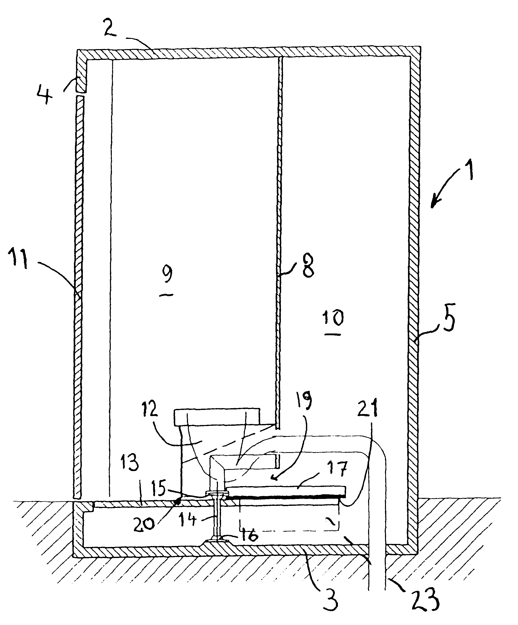
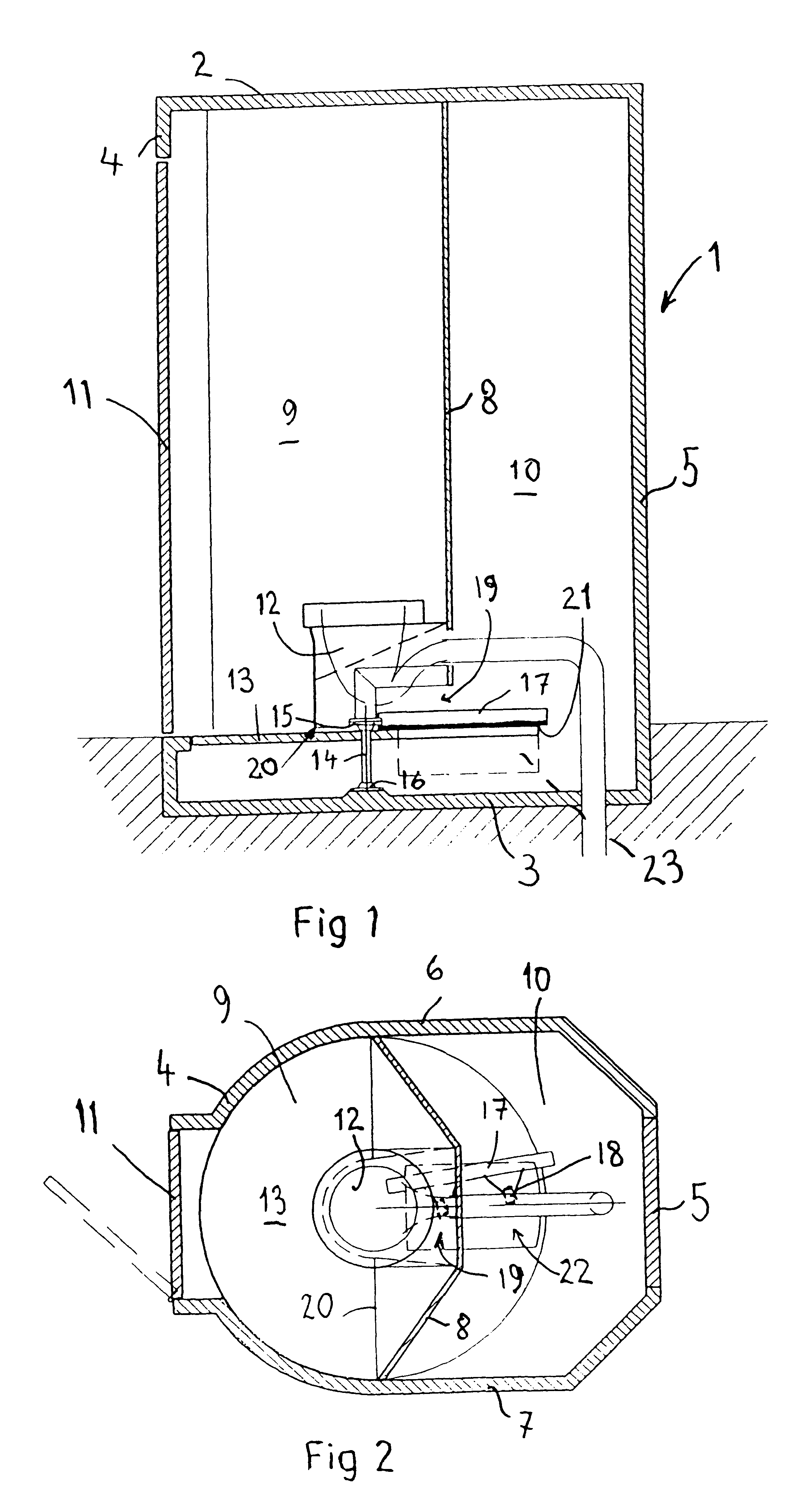
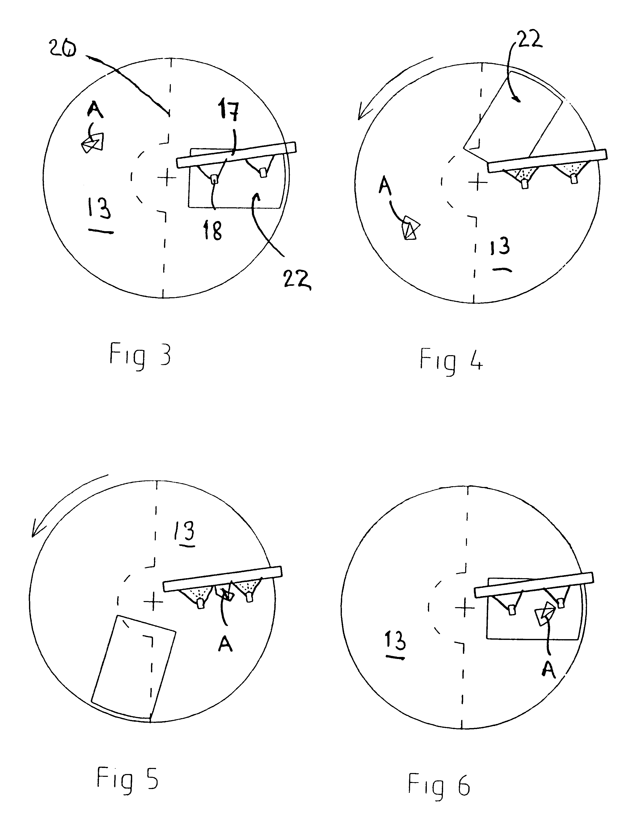
The automatic public toilet 1 disclosed in the Figures has a roof 2, a ground floor 3, a front wall 4, a rear wall 5, and two side walls 6 and 7. An inner wall 8 divides the toilet 1 into a public part 9 and a service part 10. A door 11 permits access to the public part 9. A lavatory unit 12 is contained in the public part and is supported by the inner wall 8 by any suitable means. A sink (not shown) is supported by one of the walls of the public part of the toilet.

The lavatory unit 12 used in the embodiment shown can be any self-cleaning lavatory unit on the market, such as a lavatory unit commercialised by Sanitaire Equipement, France under the trade mark HYGIFLO.RTM.. The cleaning device of this unit consists essentially of a rotatable seat, a wiper and an outlet for cleaning liquid located immediately before the wiper in the direction of the movement of the seat. The wiper and outlet are swingable from an inactive position to an active position. The self-cleaning device includes...


PUM


Abstract

An automatic public toilet for outdoor use has a public part confined by a roof, four walls and a floor, and comprises a lavatory unit including a toilet seat and bowl, the lavatory unit being supported on a wall of the toilet, wherein the floor is movable into and out of the public part of the toilet and the cleaning device for the floor is placed outside the public part. The floor is rotatable around a vertical axis.

Description

CROSS-REFERENCES TO RELATED APPLICATIONSThis application claims the benefit of European Patent Application No. 99850076.3, filed May 6, 1999.1. Field of the InventionThe present invention relates to an automatic public toilet for outdoor use having a public part confined by a roof, four walls, and comprising a lavatory unit including a toilet seat and bowl, the lavatory unit being supported on a wall of the toilet, wherein the floor is movable into and out of the public part of the toilet and the cleaning device for the floor is placed outside the public part.2. Description of the Related ArtIn order to provide a fresh and hygienic appearance for the user thereof, public toilets of the kind referred to above are automatically cleaned after use. Public toilets of the kind referred to above is known from DE-Al-40 06 676 and WO 94 / 01627, the floor in those toilets consisting of the upper part of an endless conveyer. The use of an endless conveyer requires a relatively large space under...

Claims


Application Information

Patent Timeline
Patent Type & Authority Patents(United States)
IPC IPC(8): E03D9/00
CPCE03D9/002
Inventor FORSLUND, GORAN
Owner DANFO SANITETSSYST
Learn More