
Surgical lead paddle

a surgical and lead-type technology, applied in the field of implantable medical devices, can solve the problems of affecting paresthesia, difficult anchoring of percutaneously inserted leads, and affecting paresthesia, and achieve the effect of reducing the space in which to place leads, reducing the risk of fracture, and reducing the safety of patients

Active Publication Date: 2010-04-13
MEDTRONIC INC
View PDF36 Cites 123 Cited by
  • Summary
  • Abstract
  • Description
  • Claims
  • Application Information

AI Technical Summary

Benefits of technology

[0012]The present invention provides for an implantable medical lead for electrical stimulation. The medical lead is comprised of a paddle. The paddle having at least one electrode electric

Problems solved by technology

Although spinal stimulation has proven effective for pain relief, there are problems associated with it, especially stimulation in the high cervical region.
This poses a significant problem when placing the stimulation leads since the space in which to place the leads is diminished substantially.
Percutaneously inserted leads can be used for pain reduction / elimination, however, there are problems associated with these leads.
Percutaneously inserted leads are difficult to anchor and have a tendency to become dislodged.
Even if the initial placement is accurate, lead migration can occur which can adversely affect paresthesia.
Further, if the percutaneously inserted lead migrates enough to touch an incoming dorsal root, this can be very painful for the patient.
This is a significant problem since percutaneous leads provide only limited means to change the area of stimulation if the lead migrates or if the needs of the patient change.
Thus, the stimulation area for percutaneous leads remains consequently small and because of this even a slight movement of the lead, especially laterally, can adversely affect paresthesia.
Another possible problem with percutaneous leads is their thickness is relatively large in comparison with the thickness of the dura mater in the high cervical region.
Because of the limited space in the high cervical region, if the lead is inserted improperly or if the lead migrates when placed in the cervical region where the dura mater is very thin, the percutaneous lead could possibly cause compression of the dura mater into the spinal cord causing discomfort, excess pain, and even paralysis.
Current technology does not allow the manufacture of desirably thin silicone rubber paddles suitable for locations with small extradural spaces such as the high cervical region due to production tolerances, coverage specifications, and internal anti-stretch components, which must be added to make the lead less elastic.
Further, thin rubber coverage on silicon rubber paddles over internal components; such as the electrodes, are known to lack durability.
Since the physician is trying to fit a rectangular lead into a cylindrical passage there is the potential for compression of the dura mater on the spinal cord.
Therefore, inserting this rectangular lead still risks compression of the dura mater into the spinal cord causing discomfort, excess pain, and even paralysis.

Method used


Image

  • Surgical lead paddle
  • Surgical lead paddle
  • Surgical lead paddle

Examples


Embodiment Construction

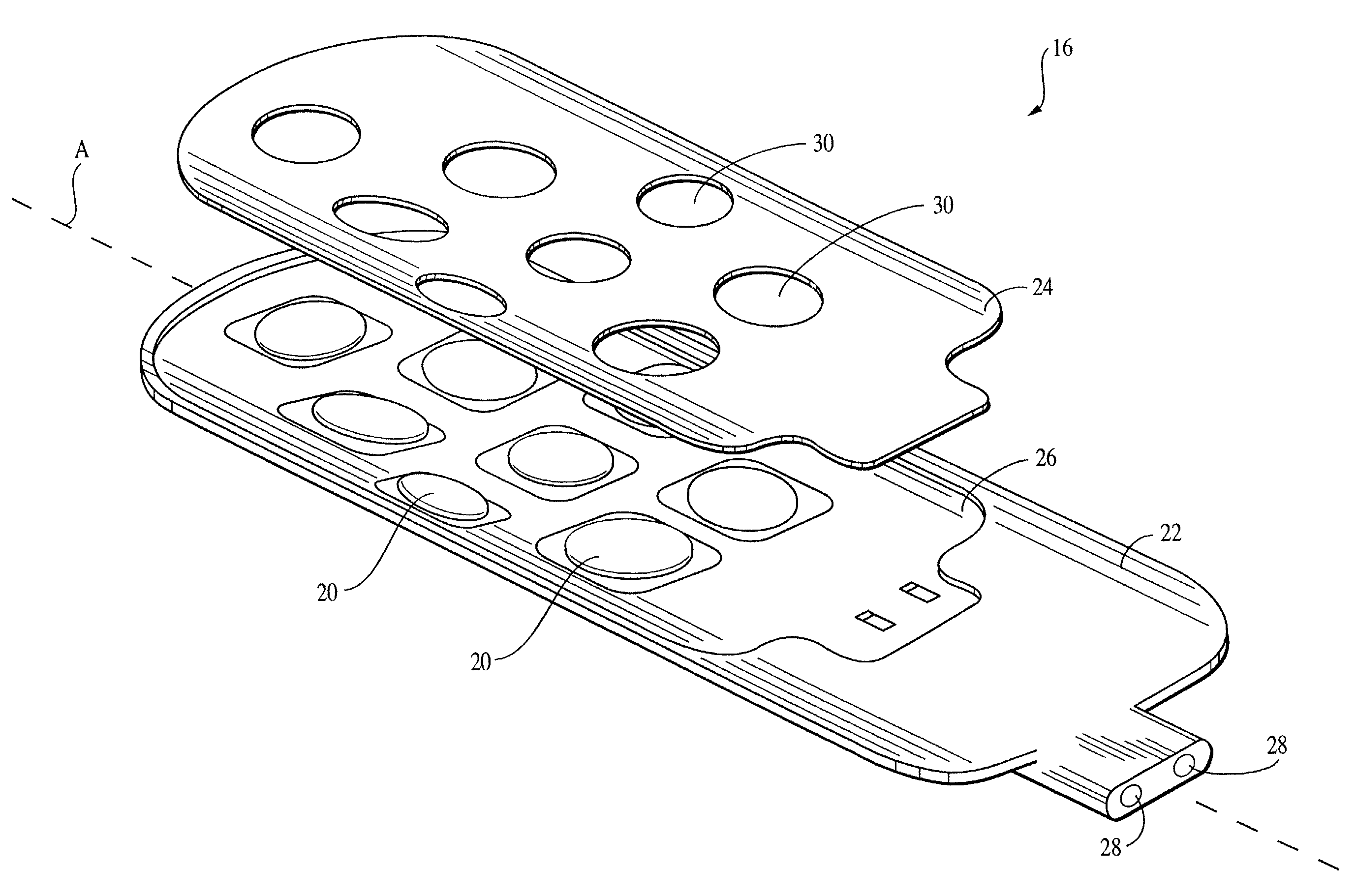
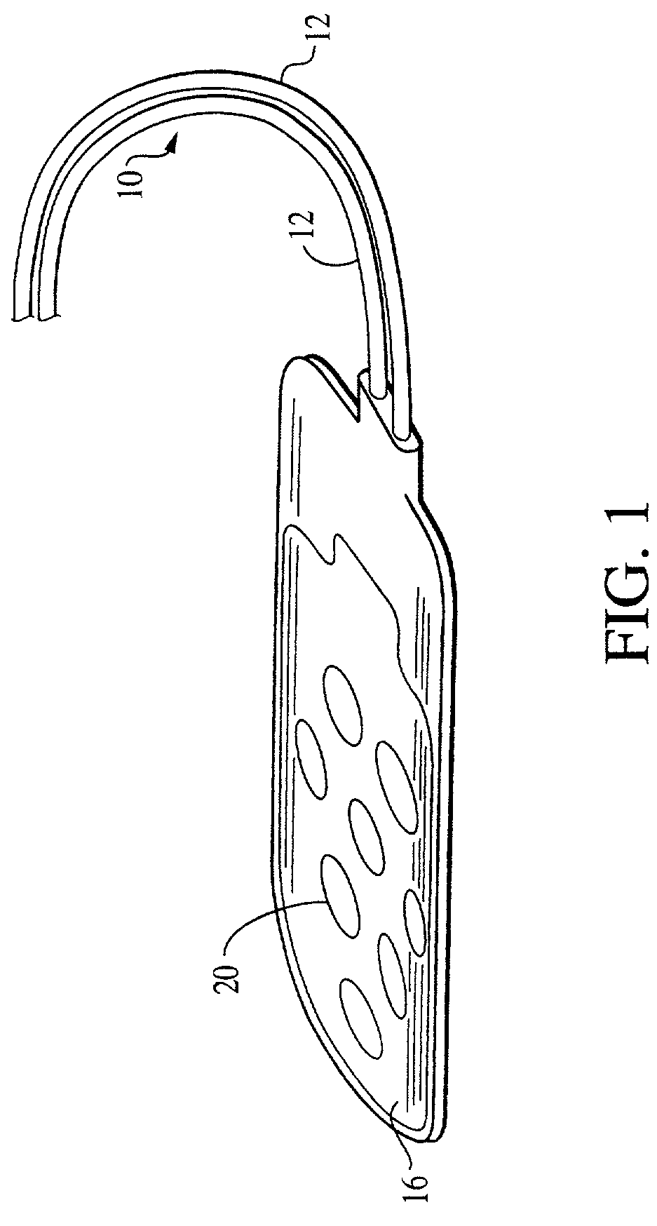
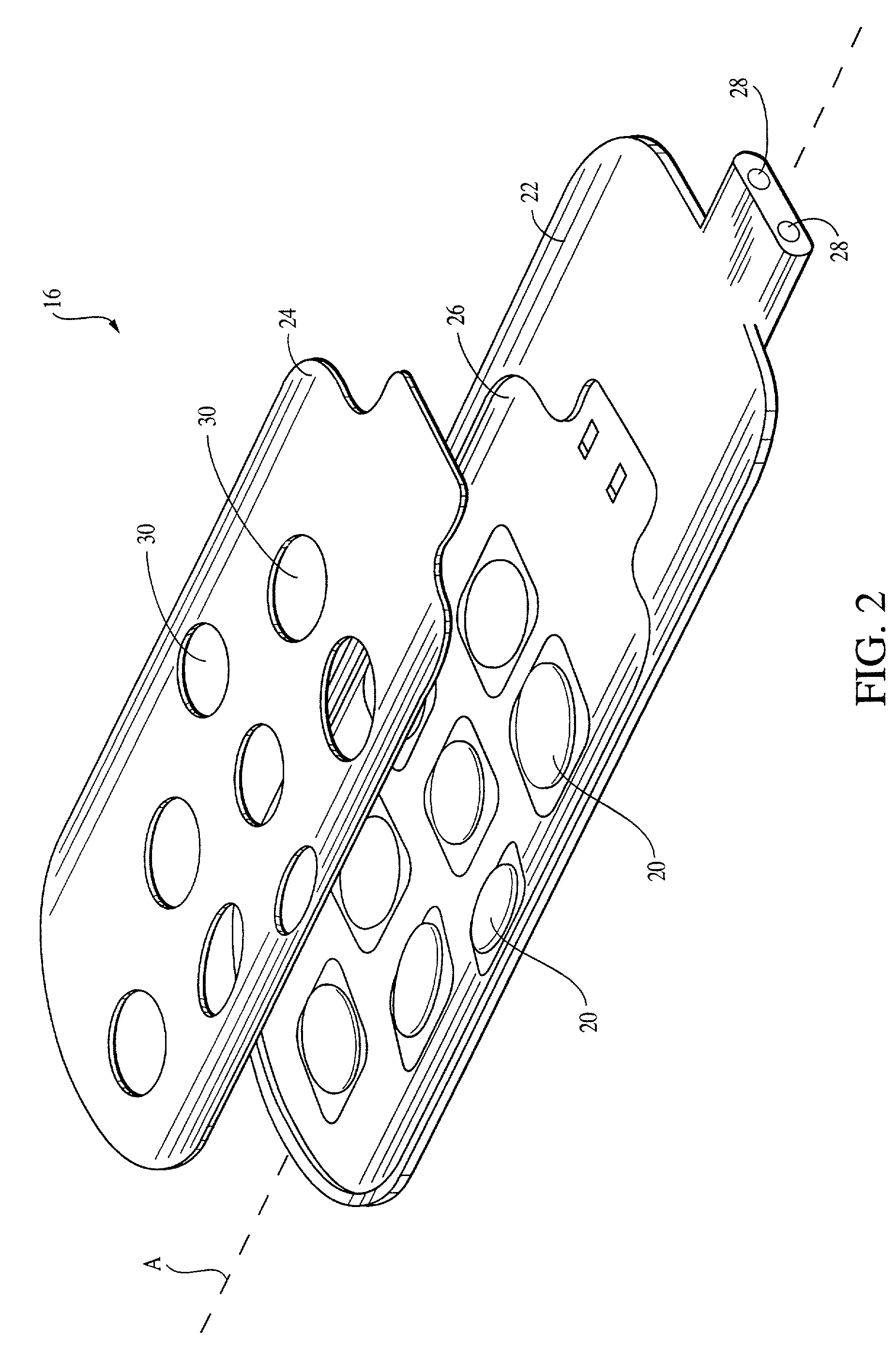
[0024]To assist in an understanding of the invention, a preferred embodiment or embodiments will now be described in detail. Reference will be frequently taken to the figures, which are summarized above. Reference numerals will be used to indicate certain parts and locations in the figures. The same reference numerals will be used to indicate the same parts or locations throughout the figures unless otherwise indicated.

[0025]The present invention is not limited to only high cervical implantation or spinal stimulation leads, and may be employed in many of various types of therapeutic or diagnostic devices including spinal cord, peripheral nerve, deep brain, and deep brain stem stimulation leads. It is to be further understood, moreover, the present invention may be employed in many of various types of therapeutic or diagnostic leads and is not limited only to the high cervical leads. For purposes of illustration only, however, the present invention is below described in the context o...


PUM

PropertyMeasurementUnit
Thicknessaaaaaaaaaa
Thicknessaaaaaaaaaa
Thicknessaaaaaaaaaa

Abstract

The present invention provides for an improved apparatus and method for electrical stimulation. A paddle having a thickness up to 0.030 inches is implanted adjacent the spinal cord dura mater to reduce the likelihood of paralysis due to stress on the spinal cord attributed to bulkier leads. The paddle is then positioned so that at least one of a plurality of electrodes is positioned over the area of the spinal cord requiring pain treatment; and then electric stimulation is applied to the electrodes to effect pain treatment. In another embodiment the paddle is curved about a vertical axis to substantially match the shape of a human spinal cord dura mater to help reduce lead migration.

Description

FIELD OF THE INVENTION[0001]The present invention generally relates to the field of implantable medical devices, and more particularly to a medical electrical lead providing improved implantation capabilities.BACKGROUND OF THE INVENTION[0002]Electrical stimulation of electrically excitable tissue such as the brain and / or nerve tissue of the spinal cord or peripheral nerve can result in pain reduction and / or elimination for a living organism having the electrical stimulation performed. Thus, for example, medical leads having electrode contacts have been implanted near the spinal column of the human body to provide pain relief for chronic intractable pain. The nerve tissue within the spinal column is stimulated electrically to reduce pain sensations at other parts of the body.[0003]Depending on the location of the pain sensation, and the particularities of each different human body, the parameters of the stimulation signals applied near the electrically excitable tissue are adjusted t...

Claims


Application Information

Patent Timeline
IPC IPC(8): A61N1/00A61N1/05
CPCA61N1/0553Y10T29/49174
Inventor CROSS, JR., THOMAS E.RACZ, GABOR
Owner MEDTRONIC INC
Learn More