
Apparatus for high pressure pumping or homogenizing liquids

a technology of high pressure pump and liquid, which is applied in the direction of applications, mechanical apparatus, liquid fuel engines, etc., can solve the problems of increasing heat generation, difficult to realize an efficient air cooling of the mechanisms and components included, and the electric motor acting as a prime mover for the homogenizer or high pressure pump generates considerable hea

Inactive Publication Date: 2002-02-12
TETRA LAVAL HLDG & FINANCE SA
View PDF11 Cites 15 Cited by
  • Summary
  • Abstract
  • Description
  • Claims
  • Application Information

AI Technical Summary

Benefits of technology

Yet a further object of the present invention is that the construction of the apparatus divides up the high pressure pump or homogenizer into a hygienic section and a drive section, with the result that the drive section may be sound-proofed in compliance with considerably lower standards than those required for hygienic machines.

Problems solved by technology

Above all the electric motor which acts as a prime mover for the homogenizer or high pressure pump generates considerable heat during operation.
As a result of the construction of the homogenizer, it has hitherto proved difficult to realise an efficient air cooling of the mechanisms and components included in it.
During a lengthy operational period, more and more heat is generated inside the casing of the machine, which may finally lead to failure, because of the fact that the load-supporting capability of the oil in the bearings is reduced considerably with increasing ambient temperature.
Nor have prior art constructions hitherto afforded any possibility of leading off or making use of the surplus heat.
Prior art designs of machine concept and casing have also resulted in the various parts in a homogenizer being difficult to access for service.

Method used


Image

  • Apparatus for high pressure pumping or homogenizing liquids
  • Apparatus for high pressure pumping or homogenizing liquids
  • Apparatus for high pressure pumping or homogenizing liquids

Examples


Embodiment Construction

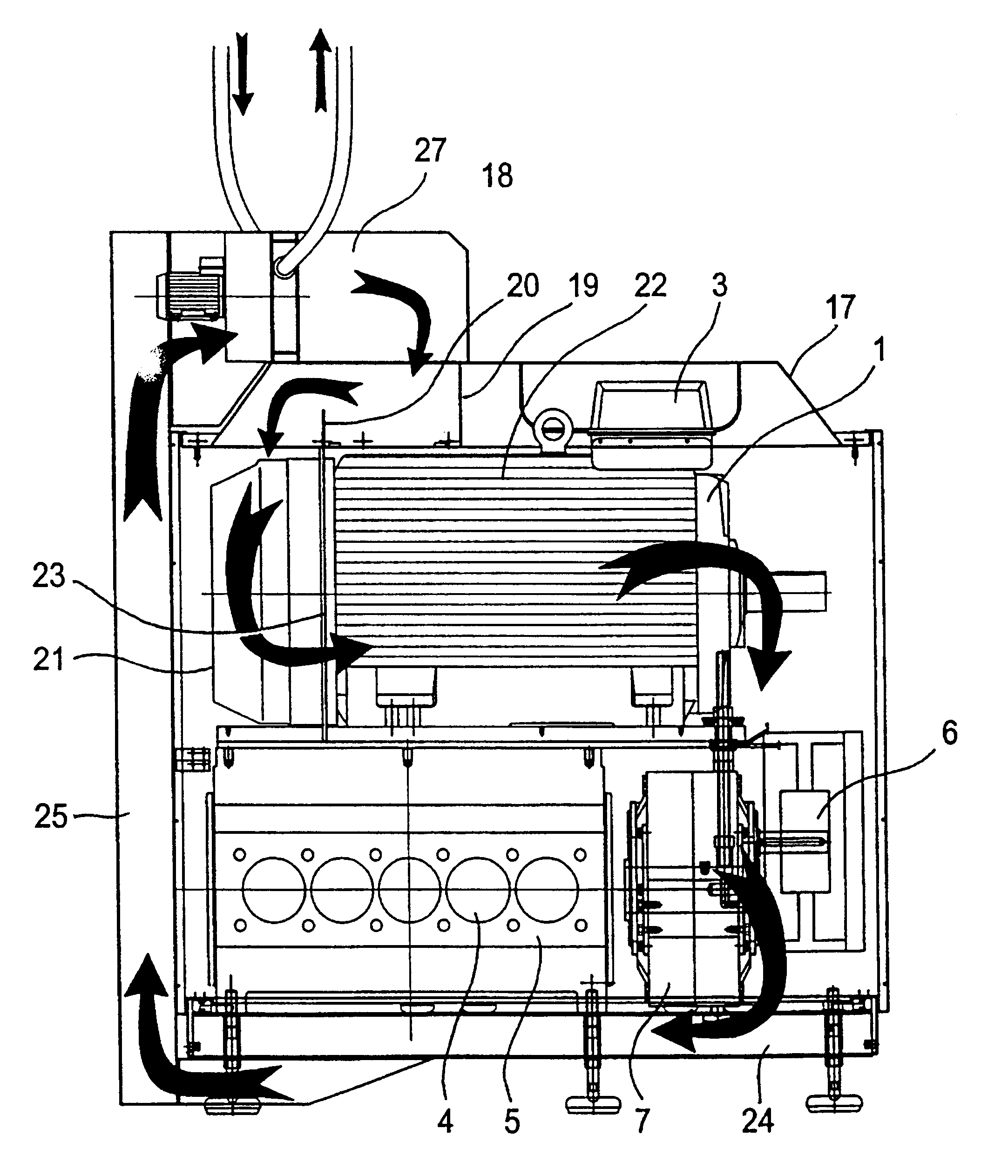
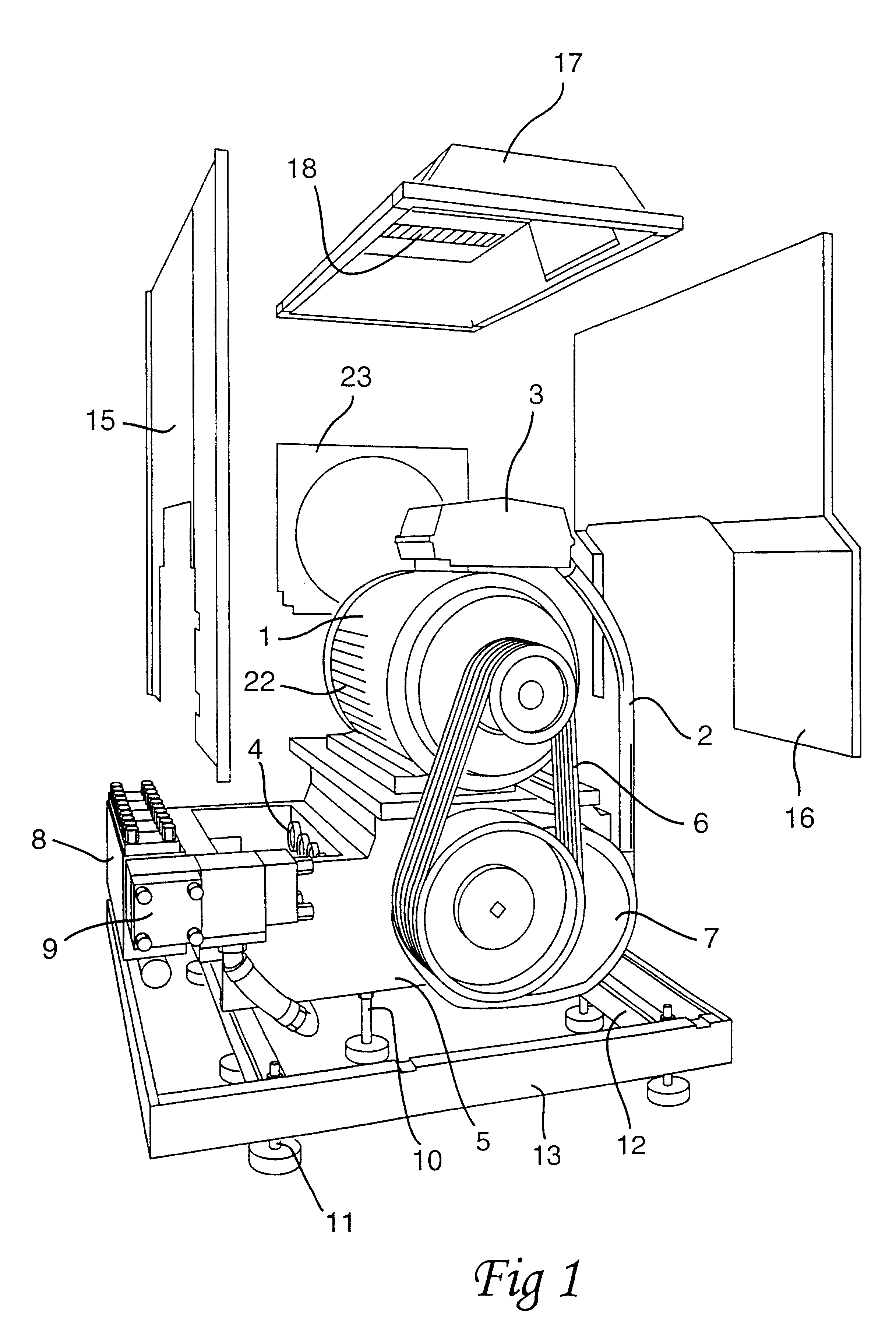
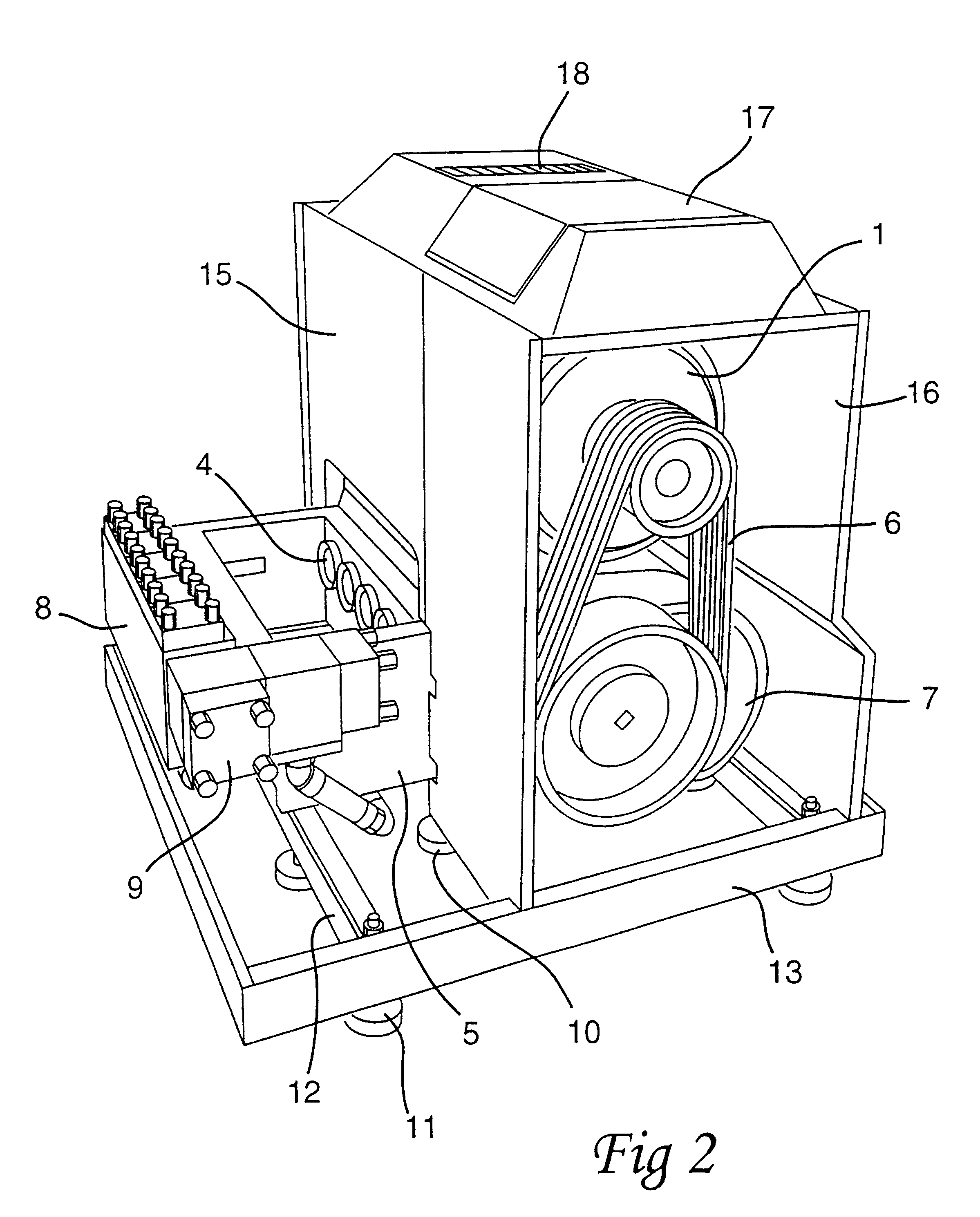
The apparatus for high pressure pumping, i.e. a high pressure pump or alternatively a homogenizer, is driven by a powerful electric motor 1. The electric motor 1 is connected to a power source (not shown) by the intermediary of a cable line 2 from its protective terminal box 3.

The apparatus further includes a pump section which consists of a number of pump plungers or pistons 4 and a pump block 8. The pistons are disposed to reciprocate in cylinders. The pump pistons 4 are connected to a crank mechanism which is housed in a robust crankcase 5 preferably of cast iron. The number of pump pistons 4 and their diameter may vary depending upon the capacity and the pressure for which the apparatus is intended.

Between the electric drive motor 1 and the pump section, there is disposed a transmission mechanism which substantially consists of one or more drive belt trains 6, a gearbox 7 and the above-mentioned crank mechanism. The transmission mechanism caters for the conversion of the rotary ...


PUM


Abstract

An apparatus for high pressure pumping or homogenizing of liquids has a drive motor with a transmission mechanism and a pump section. The transmission mechanism includes a belt train, a gearbox and a crank mechanism which is housed in a crankcase. The pump section includes a pump block, valves, and pistons which are connected to the crank mechanism. The transmission mechanism converts the rotary movement of the drive motor into the reciprocating movement of the pump pistons. The drive motor is placed directly above the crankcase and is surrounded on two sides by partitions which are interconnected by a roof. The partitions form, together with the roof, an air channel such that the driving parts of the apparatus may be cooled in a simple and efficient manner. By use of various arrangements peripheral to the apparatus, the air may be led off or recycled after cooling and recovery of the heat.

Description

The present invention relates to an apparatus for high pressure pumping or homogenizing liquids, and comprises a drive motor with transmission mechanism which consists of a belt train, a gearbox and crank mechanism, as well as a pump section with pump block, valves and pistons connected to the above-mentioned crank mechanism, the crank mechanism being housed in a crankcase.A high pressure pump substantially consists of a powerful electric motor, a transmission mechanism comprising belt train, gearbox and crank mechanism, as well as a pump section with pump block, valves and a number of plungers or pistons. The crank mechanism is housed in a crankcase. The rotary movement of the electric motor is converted by means of the transmission mechanism into the reciprocating movement of the pistons. The high pressure pump moreover includes peripheral equipment, such as operating devices, pressure gauge, lubricating system and electric system.A common field of application for a high pressure ...

Claims


Application Information

Patent Timeline
Patent Type & Authority Patents(United States)
IPC IPC(8): A01J11/16A01J11/00F04B53/00F04B53/08F04B41/00F04B17/03F04B47/00
CPCF04B53/08A01J11/16Y02P60/85Y02P60/87
Inventor PERSSON, RICHARDJOHANSSON, CLAES-GORAN
Owner TETRA LAVAL HLDG & FINANCE SA
Learn More