
Pivoting frame suspension scooter

a frame and scooter technology, applied in the field of motor powered scooters, can solve the problems of inability to solve the problem, no shock-absorbing frame has been integrated to absorb road irregularities, and the swing arms used in motorcycles for independent movement of the rear wheel are impractical, so as to increase or decrease the shock-absorbing ability of the shock-absorbing frame. effect of 1

Inactive Publication Date: 2002-01-15
MARTIN MFG
View PDF6 Cites 34 Cited by
  • Summary
  • Abstract
  • Description
  • Claims
  • Application Information

AI Technical Summary

Benefits of technology

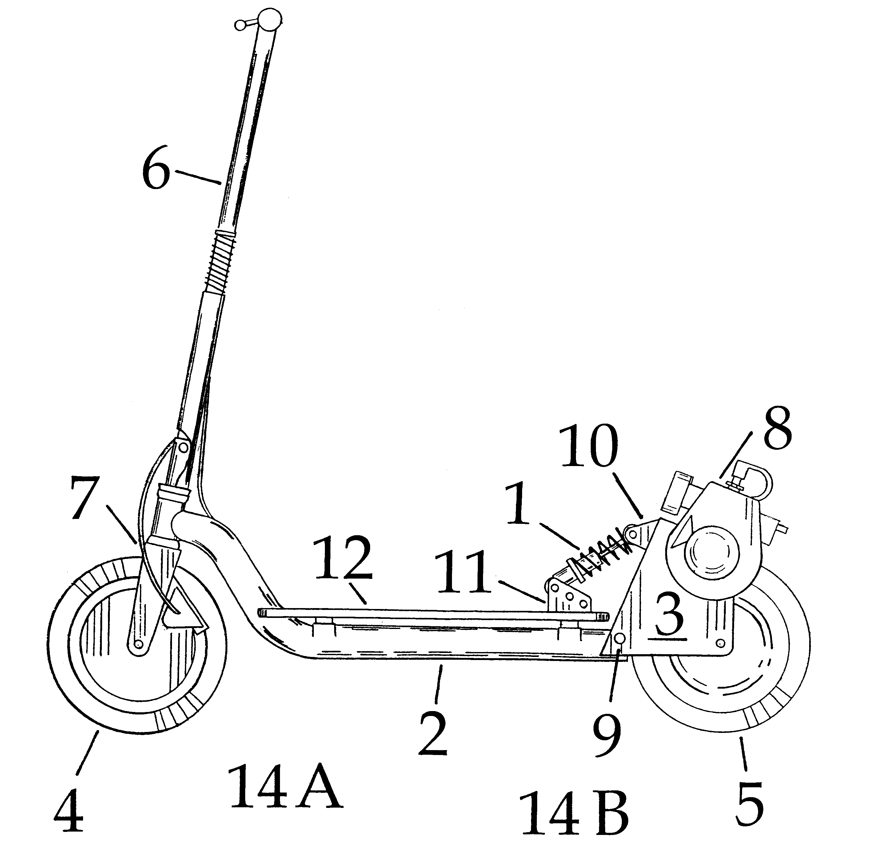
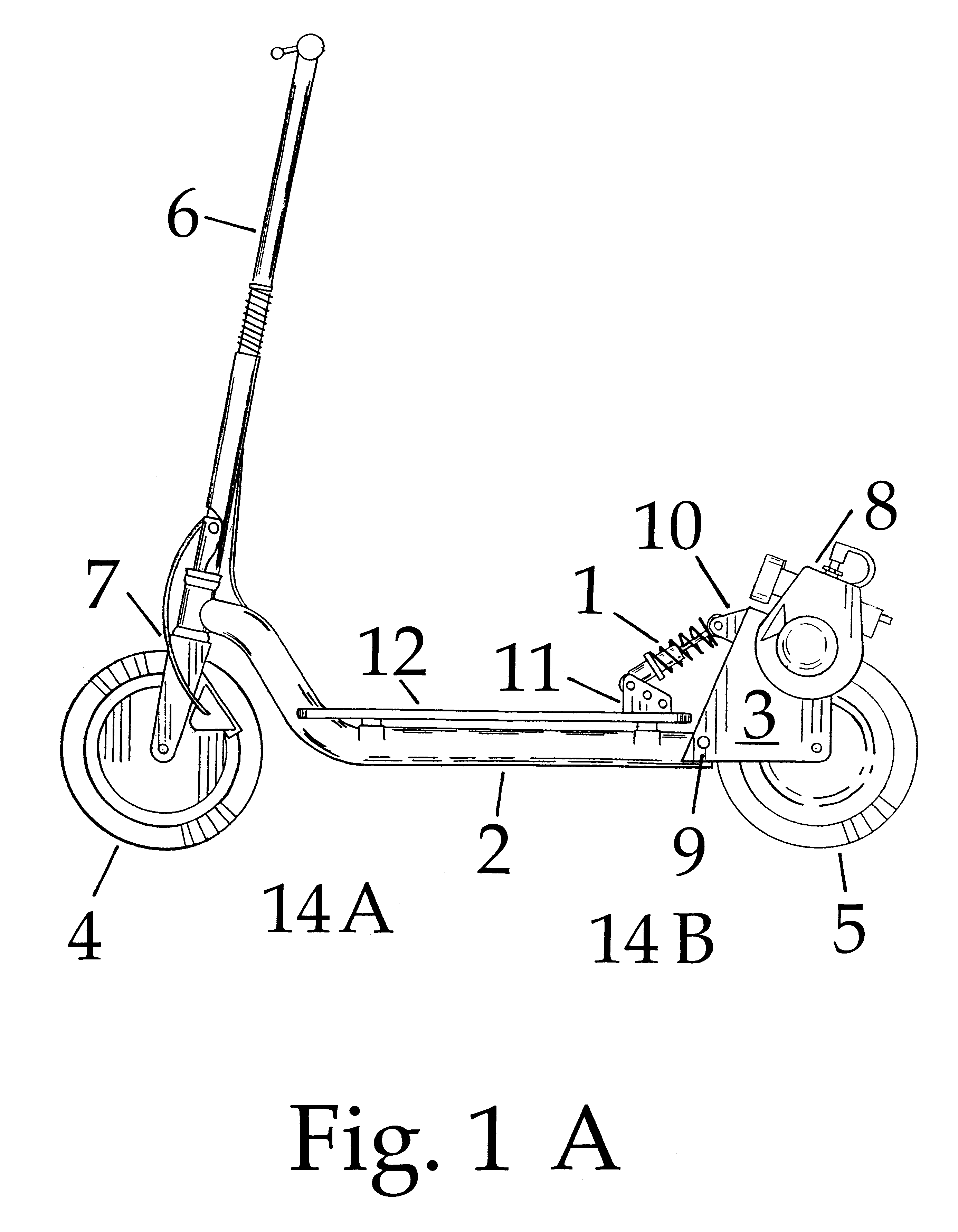
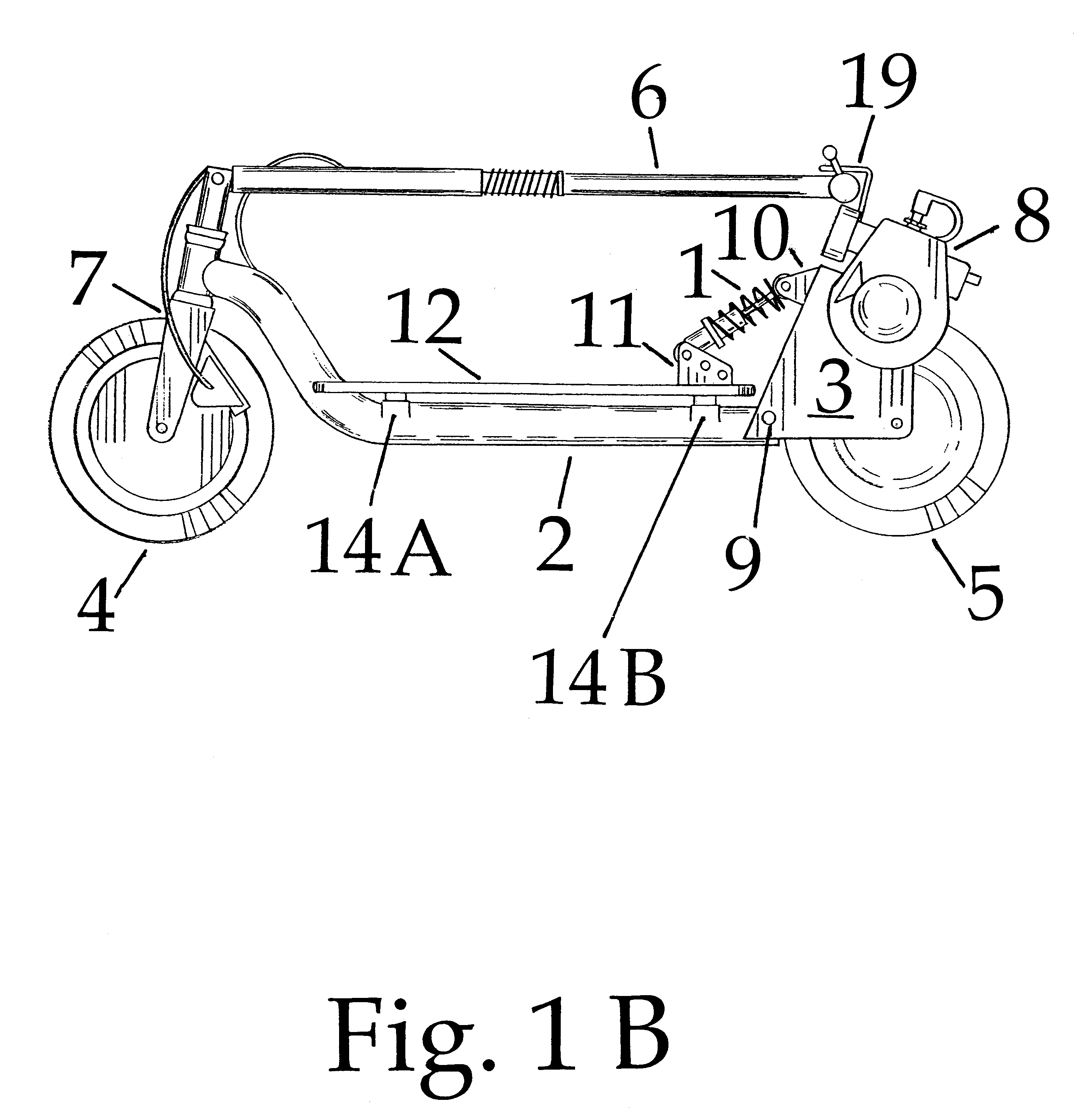
In FIG. 1 the front frame 2 is connected to the rear frame 3 by a horizontal pivot 9. One end of a shock absorber 1 is attached to the front frame 2 by shock mount front frame 11. The other end of the shock absorber 1 is connected to the rear frame 3 by a shock mount rear frame 10. FIGS. 2A, B, and D shock mount 10 or 11 can have multiple holes spaced apart from each other for receiving the shock absorber 1 ends. This allows the user to increase or decrease the shock absorbing ability of the shock absorber 1 by increasing or decreasing the leverage force input into the shock end. These spaced holes in the shock mount 10 or 11 are placed so that the shock absorber 1 can be moved from hole to hole without affecting the original orientation of the frame halves to each other. The rider stands on the riding platform 12 when operating scooter FIG. 3 when scooter transverses an uneven surface, the weight of the rider presses down on the riding platform 12, riding platform 12 is connected to the front frame 2. Since the front wheel 4 holds one end of the scooter upright, the force of the rider's weight is directed toward the horizontal pivot 9 in the frame. The rear drive wheel 5 also resists downward movement and directs downward force to the horizontal pivot 9. Subsequently the front frame 2 and the rear frame 3 rotate in relation to each other allowing riding platform 12 to be displaced downward. The shock absorber 1 resists the downward displacement, in this way the suspension system for the rider is accomplished. It will be apparent to those skilled in the art that various changes and modifications may be made therein without departing from the spirit of the invention or from the scope of the amended claims.

Problems solved by technology

This made for difficulty in driving over rough terrain, this problem has been partly solved by the implementation of shock absorbing means in the addition of pneumatic tires, but these scooters still had significant problems driving over rough terrain, U.S. Pat. No. 6,012,539 shows an all terrain scooter with pneumatic tires, this failed to solved the problem of driving over an uneven terrain because the pneumatic tires did not have sufficient shock absorbing capacities.
However, due to the simplicity of folding scooters, no one has incorporated shock-absorbing frame to absorb road irregularities.
Because placement of the motor required close proximity to the rear wheel, swing arms for independent movement of the rear wheel as used in motorcycles was impractical due to the length of the swing arm and forward placement of the motor.

Method used


Image

  • Pivoting frame suspension scooter
  • Pivoting frame suspension scooter
  • Pivoting frame suspension scooter

Examples


Embodiment Construction

Referring particularly to the drawings by characters of reference, FIG. 1A discloses a motorized suspension scooter having a rider's platform 12, the top surface of which provides a platform for the feet of the user in which the board is supported by the front frame 2 and connected by one or more brackets 14a and 14b. FIG. 1 Front frame 2 can be of any material which lends structure and resistant to load inputs, such materials might include, tubing, plate, or a combination of such. FIG. 4 steering handle 6 is down over and parallel to rider's platform 12. The steering handle 6 is of a type having a spring biased reciprocating sleeve 15 fitting over a hinge 17 when spring biased reciprocating sleeve 15 over hinge 17 steering handle 6 is maintained vertical. FIG. 1B and FIG. 4 when spring biased reciprocating sleeve 15 is moved away from hinge 17; steering handle 6 can be bent to the horizontal disposition. The steering handle can be secured at hook latch 19 in the horizontal position...


PUM


Abstract

An improved motorized scooter utilizing suspension provided with a large tubular chassis having two central brackets, supporting a rider's platform. The front of the tubular chassis bends upward through a notch in the platform upward above the front wheel to support a steering head tube. The steering head tube supports a fork which holds the front wheel. The rear wheel is contained in a supporting bracket which also holds the engine relative to the rear wheel allowing it to be operatively connected. The central tubular member is pivoted somewhere along its length so that the frame halves can rotate in respect to each other along the pivot point. The long lever arm provided by utilizing the frame as a suspension element allows for greater terrain following characteristics due to the increased leverage. Rotation between frame halves is resisted by a shock absorber with either end connected to the respective frame halves. When driving over uneven terrain, the weight of the rider forces down upon the rider's platform which is connected to one or the other frame halves, this suspension system allows the rider to transverse uneven terrain with greater comfort, control and safety.

Description

1. Field of InventionThis Invention relates to motor powered scooters. More particularly a construction of a suspensioned all terrain scooter is disclosed in which a frame supporting a platform for standing rider is supported on a large central tubular member. The central tubular member is pivoted somewhere along its length so that the frame halves can rotate in respect to each other along the pivot line. Rotation between frame halves is resisted by a shock absorber with either end mounted to the respective frame halves. When driving over uneven terrain, the weight of the rider forces down upon the rider's platform, which is connected to one or the other halves of the frame. Subsequently the frame halves pivot allowing the platform a downward motion, which is absorbed by the shock absorber, which is connected to the two frame halves, this suspension system allows the user to transverse uneven terrain with greater comfort, control and safety.2. Background ArtAll terrain-motorized sco...

Claims


Application Information

Patent Timeline
Patent Type & Authority Patents(United States)
IPC IPC(8): B62K3/00B62K11/00B62K11/10
CPCB62K3/002
Inventor MARTIN, CHRISTOPHER V.
Owner MARTIN MFG
Learn More