Simulation method and system for organic electroluminescent device, and electroluminescent device
a technology of electroluminescent devices and simulation methods, applied in the direction of instruments, non-linear optics, analogue processes for specific applications, etc., can solve the problems of modulation of light emitted out, difficult to make any detailed study of spectral modulation, and less than satisfactory for making much more precise estimations
Inactive Publication Date: 2001-12-04
TDK CORPARATION
View PDF9 Cites 15 Cited by
- Summary
- Abstract
- Description
- Claims
- Application Information
AI Technical Summary
Problems solved by technology
However, this is still less than satisfactory for making much more precise estimations, for the reason of large errors.
In this regard, JP-A 7-240277 reveals another problem, i.e., the modulation of light emitted out of an organic EL device due to interference of light reflected at an interface between glass and a transparent electrode.
Then, it would be difficult to make any detailed study of spectral modulation without expectation of to what degree the spectra are modulated by interference caused by a parameter other than the aforesaid one.
This would in turn make the optical design of an optimized device difficult.
It is thus still diff
Method used
View moreImage
Smart ImageViewing Examples
Examples
 PUM
 Abstract
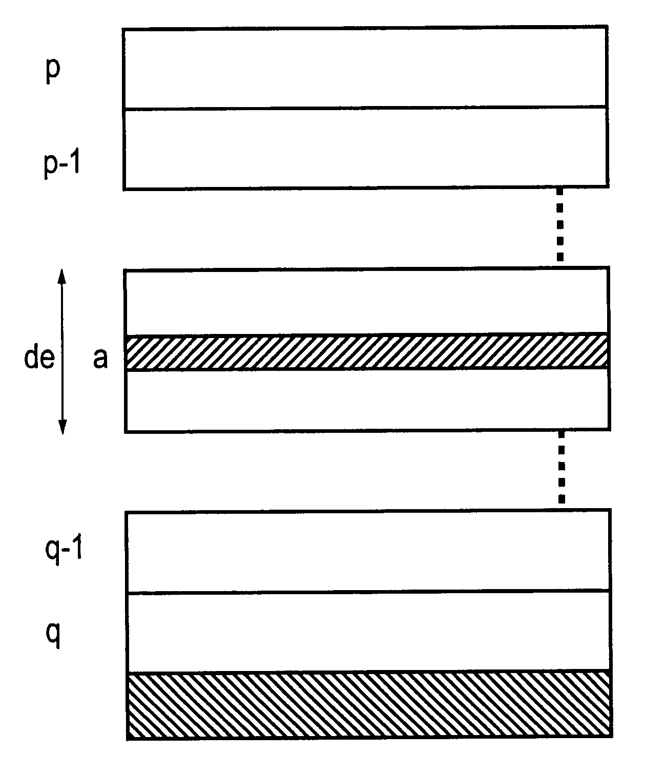
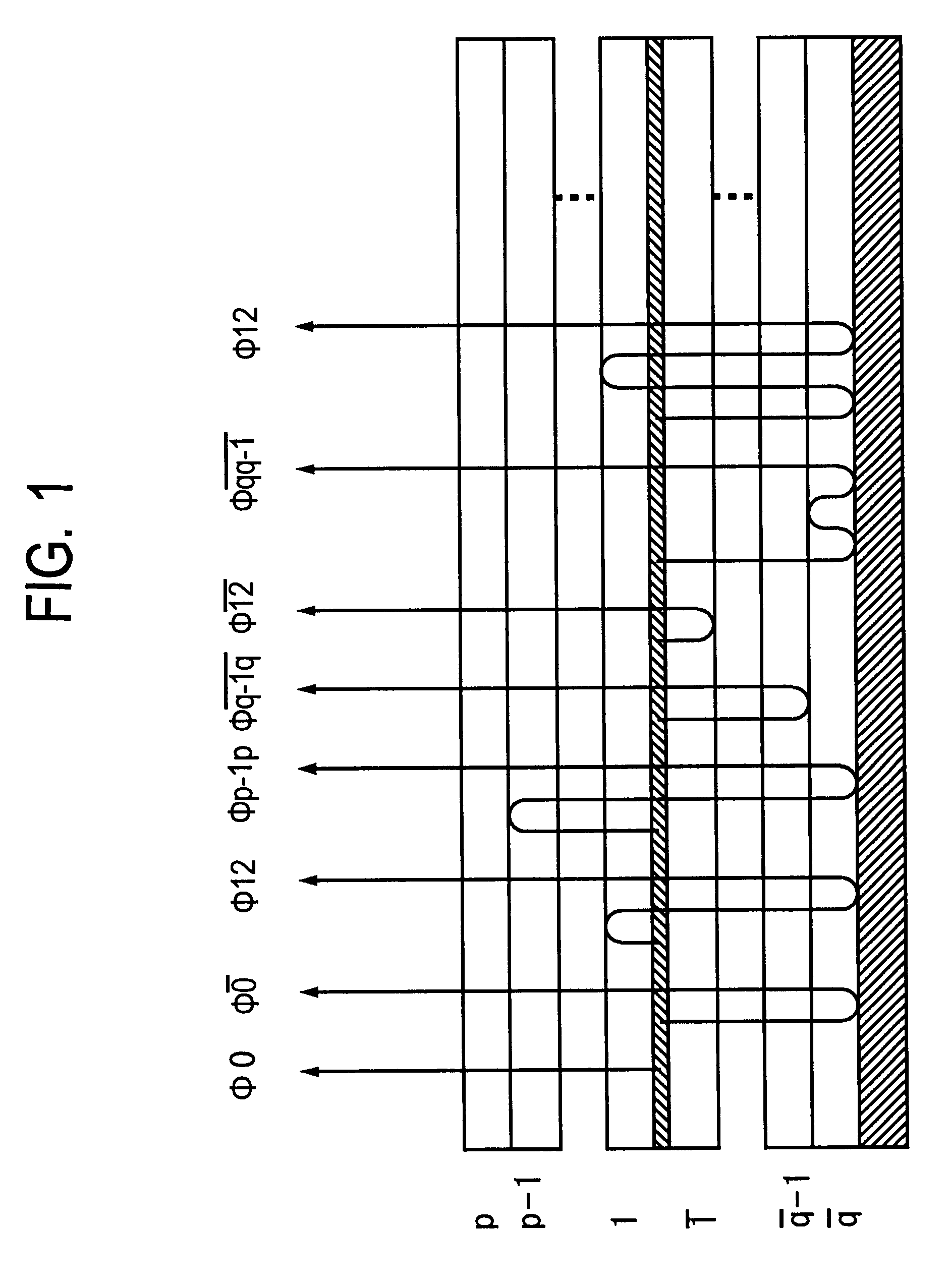
A simple mathematical model, given below, is constructed on the premise that reflected light other than light reflected at a metal surface is quantitatively taken into consideration the device to which the present invention is applied is a multilayer structure with a refractive index difference, so that only one reflection at an interface other than the metal surface can be taken into account that is, two or more reflections can be neglected. Further the concept of localized light emitting surfaces is extended to a non-localized model. The below simple mathematical model is used to treat reflected wave components so that an accurate simulation can be run.
Description
1. Field of the InventionThe present invention relates generally to an organic EL (electroluminescent) device using an organic compound. More specifically, this invention is concerned with a simulation method and system for providing an organic EL device that enable the light emitted therefrom to be effectively available with a reduced emission luminance variation, and an organic EL device as well.2. Discussion of the BackgroundIn recent years, organic EL devices have been under intensive investigation. One such device is basically built up of a thin film form of hole transporting material such as triphenyldiamine (TPD) deposited by evaporation on a hole injecting electrode, a light emitting layer of fluorescent material such as an aluminum quinolinol complex (Alq.sup.3) laminated thereon, and a metal (electron injecting) electrode of a metal having a low work function such as Mg and formed on the light emitting layer. This organic EL device now attracts attention because a very hig...
Claims
Login to View More Application Information
Patent Timeline
 IPC IPC(8): G06E3/00H01L51/50H01L51/52
CPCG06E3/005H01L51/5012H01L51/5203H10K50/805H10K50/11
Inventor KOBORI, ISAMU
Owner TDK CORPARATION
Features
- R&D
- Intellectual Property
- Life Sciences
- Materials
- Tech Scout
- Unparalleled Data Quality
- Higher Quality Content
- 60% Fewer Hallucinations
Learn More Browse by: Latest US Patents, China's latest patents, Technical Efficacy Thesaurus, Application Domain, Technology Topic, Popular Technical Reports.
© 2025 PatSnap. All rights reserved.Legal|Privacy policy|Modern Slavery Act Transparency Statement|Sitemap|About US| Contact US: help@patsnap.com


